- 17 -
Example Source Planning • Six Source Installation
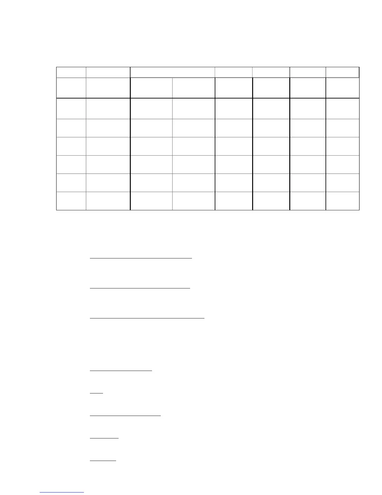
Using the example source configuration listed in the chart below, we will begin to configure
the SSD-66 (5.1) using the available options as listed in the chart on the previous page.
SOURCE NAME
DIGITAL INPUT 1
(RCA COAX)
DIGITAL INPUT 2
(RCA COAX)
MULTI-PIN
INPUT
(6 CH DIGITAL)
OPTICAL AUDIO
INPUT
(DIGITAL)
ANALOG
STEREO AUDIO
INPUT (RCA)
COMPOSITE
VIDEO INPUT
(RCA)
SOURCE 1 LASER DISC PLAYER
DIGITAL INPUT 1
(FROM RFD-1 FOR
AC-3 PLAYBACK)
MULTI-PIN INPUT
(FROM DTS-1 FOR
DTS PLAYBACK)
OPTICAL INPUT
(FOR PCM 2 CH
AUDIO PLAYBACK)
VIDEO INPUT 1
SOURCE 2 VCR STEREO INPUT 1 VIDEO INPUT 2
SOURCE 3 TV/CABLE STEREO INPUT 2 VIDEO INPUT 3
SOURCE 4 DSS STEREO INPUT 3 VIDEO INPUT 4
SOURCE 5 CD PLAYER
DIGITAL INPUT 2
(PCM DIGITAL 2
CHANNEL AUDIO)
SOURCE 6 CASSETTE STEREO INPUT 4
DIGITAL COAX (RCA) INPUTS FOR EITHER
AC-3 OR TWO CHANNEL PCM PLAYBACK
FOR TWO CH PCM
PLAYBACK
FOR 2 CH ANALOG
PLAYBACK
VIDEO FOLLOW
AUDIO INPUTS
FOR DTS
PLAYBACK ONLY
Again, as previously stated, we can begin to connect source components to the SSD-66 (5.1).
Use the chart on the previous page as a guide to make certain that the A/V Links you wish to
use are available in the SSD-66 (5.1)'s software.
Step 1 Laser Disc Players AC-3 Connection • Connect the Laser Disc players AC-3 output to the RFD-1
AC-3 RF Demodulator and the RFD-1's output to the SSD-66 (5.1)'s Digital 1 Input. The Laser Disc
Players Composite Video Output can be connected to the SSD-66 (5.1)'s Video 1 Input.
Step 2 Laser Disc Players DTS Connection • Connect the Laser Disc players digital audio coax output to
the DTS-1 and the DTS's multi-pin output to the SSD-66 (5.1)'s multi-pin input. The Laser Disc
Player's video output has already been connected in Step 1.
Step 3 Laser Disc Players Non-AC-3 Connection (PCM Audio) • Since this example uses six sources (the
maximum without the use of an external switcher), special attention needs to be paid to the full use
of the remaining two digital inputs. Since the CD player has only a coax digital audio output and the
Laser Disc has both an optical and digital coax output, we will use the Optical Output of the Laser
Disc and connect it directly to the SSD-66 (5.1)'s Optical Input. The Laser Disc Player's video
output has already been connected in Step 1.
Step 4 TV Tuner or Cable Box • The TV Tuner can be directly connected to the SSD-66 (5.1)'s Analog Input
2 with its video connected to the SSD-66 (5.1)'s Video 2 Input.
Step 5 VCR • The VCR can be connected to the SSD-66 (5.1)'s Analog Input 3 with its video connected to
the SSD-66 (5.1)'s Video 3 Input.
Step 6 Satellite or DSS Receiver • The Satellite or DSS Receiver's audio output can be connected to the
SSD-66 (5.1)'s Analog Input 4 with its video output connected to the SSD-66 (5.1)'s Video 4 Input.
Step 7 CD Player • The CD players digital coax output can be connected to the SSD-66 (5.1)'s Digital 2
(RCA) input.
Step 8 Cassette • The Cassette Player can now be connected to the last open analog input on the SSD-66
(5.1), Analog Input 1.