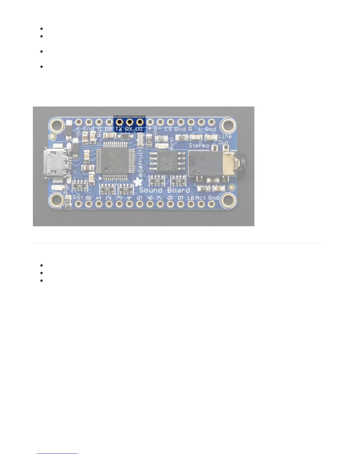
Vin - This is the primary 'battery' power input pin. Power with 3-5.5 VDC
GND - there's a couple ground pins but we suggest this one for power input. The others can be used for signal
grounds
BUS - this is the 5V that comes from the USB connector. We break this out in case you want to use it to say
charge a LiPoly battery (See the Powering It page!)
PB - this is the 'Power Button' pin, which we use for testing. Just leave it disconnected for use.
In general, you'll only want to power through the Vin and GND pins. The Vin input pin is polarity protected and can use
3V-5.5V DC input. If you want to use a larger voltage, you'll need another regulator that can bring the voltage down to
3-5V DC
UART Pins
If you want to control the Sound Board over UART Serial, you can do so by using the TX, RX and UG pins.
TX - this is the serial OUT from the board. 3.3V logic
RX - this is the serial INTO the board. We add some level shifting so you can use 3-5V logic.
UG - the UART/GPIO selector pin. Pulled high for default GPIO trigger mode. Tie to ground and reset the board
for UART mode.
 Loading...