48
INSTALLATIONCONFIGURATIONOPERATION
FURTHER
INFORMATION
INDEX
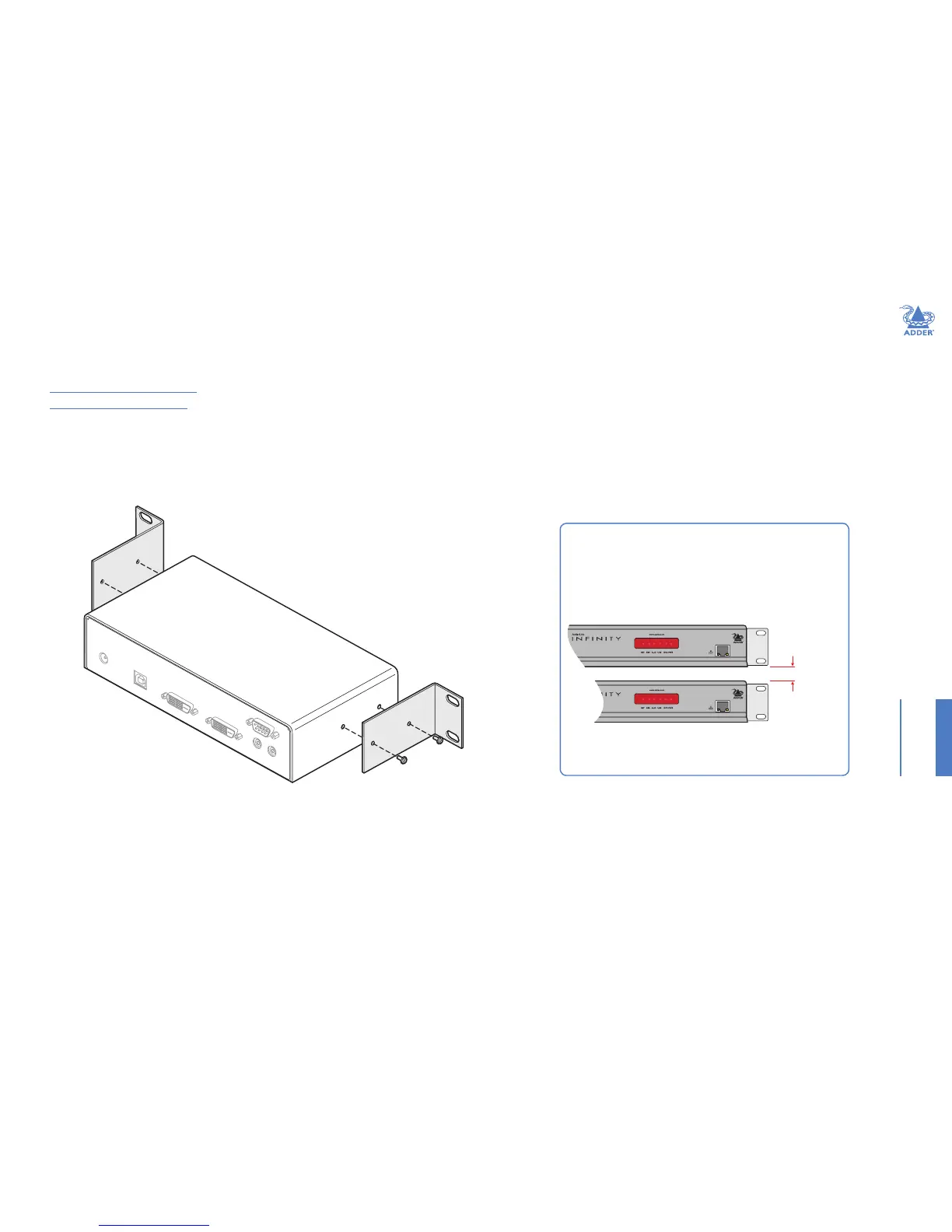
Single unit rack brackets
The optional single unit brackets (plus four screws), allow
a unit to be secured within a standard rack half width slot.
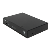
IMPORTANT - allow space for airow
The ALIF units and their power supplies generate heat when
in operation and will become warm to the touch.
Do not place them in locations where air cannot circulate
to cool the equipment. When mounting units within a rack
chassis, allow a
1
/
3
rd
U space (1.5cm) between rows of devices:
Do not operate the equipment in ambient temperatures
exceeding 40
o
C. Do not place the products in contact with
equipment whose surface temperature exceeds 40
o
C .
1
/
3
U
(1.5cm)
space for
cooling
APPENDIX H - Mounting options
There are several mounting methods for transmitter and receiver units:
• The supplied four self-adhesive rubber feet
• Optional single unit rack brackets - this page
• Optional dual unit rack brackets
• Optional VESA bracket mount