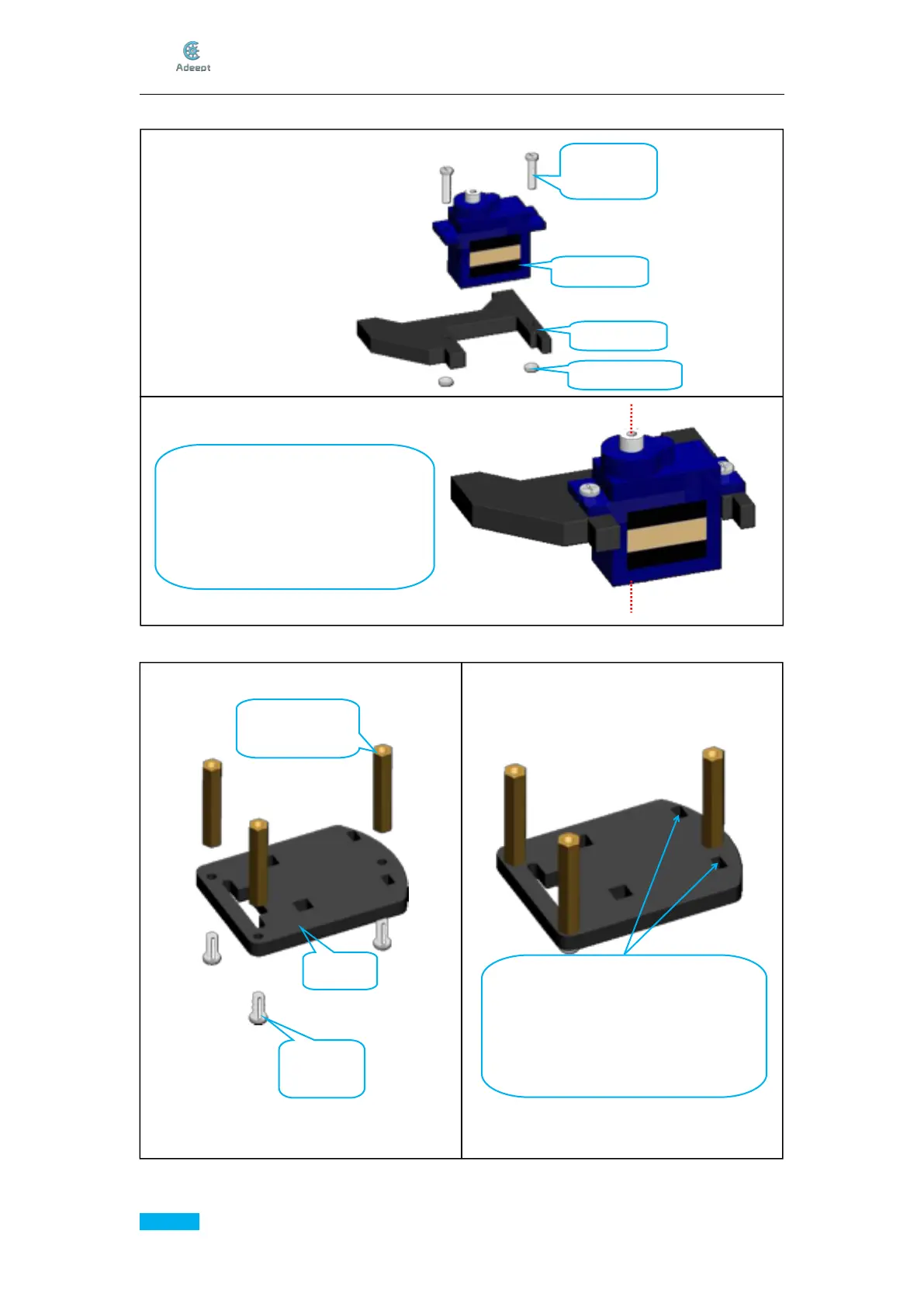
3. Take a servo and fix it with A15.
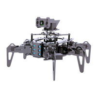
4. Fix three M3*30 Copper Standoff to A17.
Assemble the following components
Effect diagram after assembling
Install strictly according to the
position in the picture, A15 is below
the Servo, output shaft of the Servo is
to the left
Effect diagram after assembling
Assemble the following components
Install strictly according to the position
of this angle of view. Do not reverse
the A17. It can be judged according to
the position of the two square holes
indicated by the arrows.