Adept Lynx Platform User's Guide, Rev D
Page 46 of 126
Chapter 4: Payload Structures
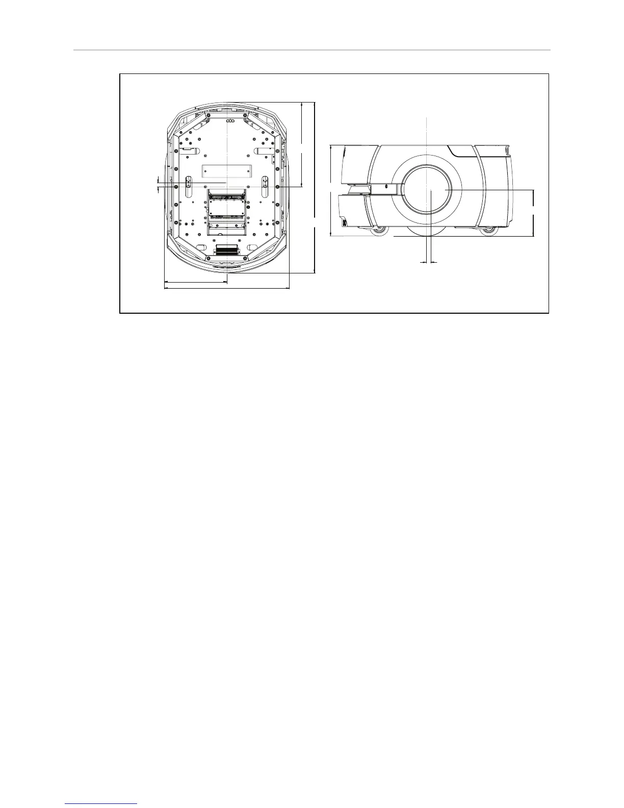
499.6
697
Wheel
Axis
345.3
CG
16.5
249.8
372
CG
188.7
CG
16.5
Units are mm
Wheel
Axis
Rear of L
ynx Platform
Front of Lynx Platform
Wheel
Axis
Figure 4-2. Center of Gravity of Platform
The three following figures show the calculations of safe placements for the center of gravity
for payload structures with the weights listed. The center of gravity, in each instance, needs to
be within the area shown. All units are mm.
NOTE:These figures show the limits of where the payload structure center of grav-
ity can be placed. You should try to keep your CG as close to the center of these fig-
ures as possible.
In the following three figures, light blue represents the payload structure, while dark (Adept)
blue represents the Adept Lynx Platform.