Adept Lynx Platform User's Guide, Rev D
Page 53 of 126
Chapter 5: Connectivity
Connection Type Description
Analog I/O HDB15M General use
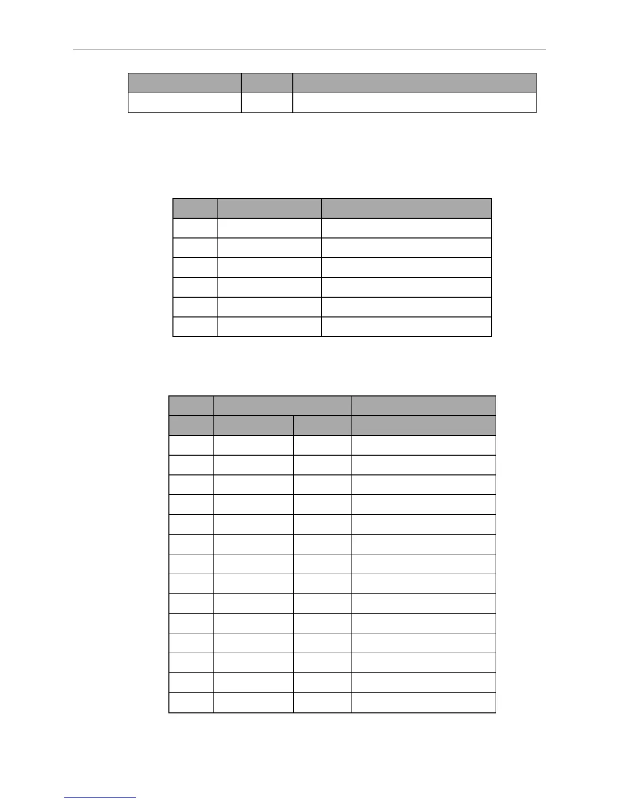
CAN Bus B
Connector type DB9F
Use CAN Bus
Pin No. Designation Notes
1, 4, 8 No Connection
2 CANL_B CAN Communication differential pair
3, 6 GND Direct GND
5 SHIELDGND Bead filter to GND
7 CANH_B CAN Communication differential pair
9 CANB_12V_OUT_SW 12 V @ 0.5 A Max (switched in SW)
Digital I/O
Connector type HDB44F
Designation
Pin No. Hardware Software Notes
1 INPUT_1.1 Input_1.1 0 – 30 V Range, R
in
= ~3.9 kΩ
2 INPUT_1.2 Input_1.2 0 – 30 V Range, R
in
= ~3.9 kΩ
3 INPUT_1.3 Input_1.3 0 – 30 V Range, R
in
= ~3.9 kΩ
4 INPUT_1.4 Input_1.4 0 – 30 V Range, R
in
= ~3.9 kΩ
5 BANK1 Common for INPUT_1.X
6 INPUT_2.1 Input_2.1 0 – 30 V Range, R
in
= ~3.9 kΩ
7 INPUT_2.2 Input_2.2 0 – 30 V Range, R
in
= ~3.9 kΩ
8 INPUT_2.3 Input_2.3 0 – 30 V Range, R
in
= ~3.9 kΩ
9 INPUT_2.4 Input_2.4 0 – 30 V Range, R
in
= ~3.9 kΩ
10 BANK2 Common for INPUT_2.X
11 INPUT_3.1 Input_3.1 0 – 30 V Range, R
in
= ~3.9 kΩ
12 INPUT_3.2 Input_3.2 0 – 30 V Range, R
in
= ~3.9 kΩ
13 INPUT_3.3 Input_3.3 0 – 30 V Range, R
in
= ~3.9 kΩ
14 INPUT_3.4 Input_3.4 0 – 30 V Range, R
in
= ~3.9 kΩ