B 300
Controlling the detector with the I/O
interface
GB 00979 - Edition 05 - March 04
1/2
Alcatel Vacuum Technology France - ATH 200 User’s Manual
Purpose of the I/O
interface
Location of the I/O
interface
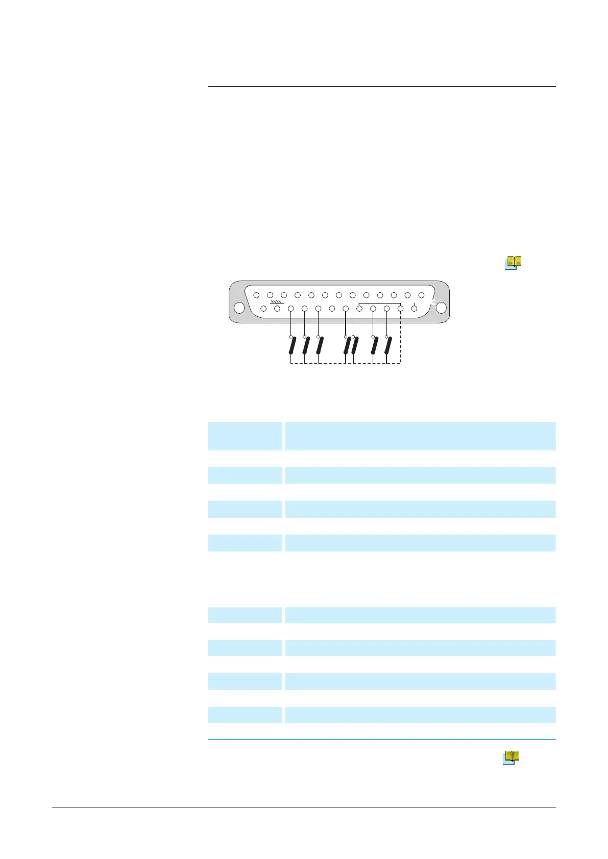
Prepare the
connector wiring
The controls
(inputs)
The signals
(outputs)
Dry contacts:
Direct current: 60 V - 60 W or 2 A max
Alternative current: 40 V - 125 VA or 2 A max
1 - 2
Sniffer mode (LDS)
3 - 4
Gross leak mode
5 - 6
High sensitivity mode
7 - 9
Test cycle start
10 - 11
Filament on
12 - 13
Helium signal > Reject Set point
19 - 15
Analog output 0 - 10 VDC (inlet pressure)
14 - 15
0 - 8 VDC analog output (Helium signal)
Note:
15 = internal ground
24 = common (external ground)
21 = common (external ground)
It is recommended to use a shielded cable which is grounded on the
connector cap.
B 210
The I/O interface makes it possible to control the leak detector with a
PLC or any other external control device.
The common points of
the controls are pins 21
and 24.
G 300
23 Interface
Contact open: the lament command is valid.
Contact closed: the lament command is invalid.
22 Calibration
Autocalibration sequence start
8 Cycle
Cycle start
20 Filament
Filament on
18 GL mode
Gross leak mode selection
17 LDS mode
Sniffing mode selection
16 Inlet vent
Vent mode selection
The I/O interface is available on a Sub D 25 pin Female connector
located on the back of the leak detector.
Alcatel Vacuum Technology France - User's Manual ASM 182/192 TD+ - ASM 192 T2D+