System Hardware Configuration
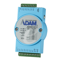
Figure 5-25: Data Stream Monitoring
Chapter 5
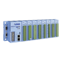
Select the IP address of the ADAM-5000/TCP Series you want to
read data, then click “Start” button. The Utility software will begin to
receive the stream data on this operation display.
ADAM-5000/TCP User’s Manual
5-21
 Loading...