v ADAM-6300 User Manual
Contents
Chapter 1 Product Overview ................................1
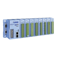
1.1 ADAM-6300 Introduction........................................................................... 2
1.2 Features .................................................................................................... 2
1.3 Hardware Introduction............................................................................... 2
1.3.1 Front Name Plate.......................................................................... 2
Figure 1.1 Front Name Plate ....................................................... 2
1.3.2 Power Connection......................................................................... 3
Figure 1.2 Power Connector........................................................ 3
1.3.3 Ethernet Connector and Grounding Screw................................... 3
Figure 1.3 Ethernet Connector and Grounding Screw................. 3
1.3.4 LED Definition............................................................................... 3
1.3.5 Dimensions ................................................................................... 4
Figure 1.4 ADAM-6300 Dimensions ............................................ 4
1.4 Package Information ................................................................................. 4
Chapter 2 Hardware Installation ..........................5
2.1 Mounting: DIN rail ..................................................................................... 6
Figure 2.1 DIN Rail Adapter......................................................... 6
2.2 Power Supply Wiring................................................................................. 6
2.3 I/O Module Wiring ..................................................................................... 7
Chapter 3 Introduction to Digital I/O ...................9
3.1 Specifications .......................................................................................... 10
3.1.1 General ....................................................................................... 10
3.1.2 Protection.................................................................................... 10
3.1.3 Environment................................................................................ 10
3.1.4 OPC UA Specification................................................................. 10
3.1.5 Modbus ....................................................................................... 11
3.2 Digital Input/Output Modules (ADAM-6350)............................................ 18
3.2.1 Specifications.............................................................................. 18
3.2.2 Application Wiring ....................................................................... 18
Figure 3.1 Application Wiring (Top View) .................................. 18
Figure 3.2 Application Wiring (Side View) ................................ 19
Figure 3.3 DO Output Wiring (Resistive and inductive load) ..... 19
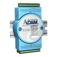
3.3 Analog Input Modules (ADAM-6317) ...................................................... 20
3.3.1 Specifications.............................................................................. 20
3.3.2 Application Wiring ....................................................................... 20
Figure 3.4 Analog Input Wiring .................................................. 20
Figure 3.5 Digital Input Wiring ................................................... 21
Figure 3.6 Digital Output Wiring................................................. 21
Figure 3.7 “U”(Upper) and Bottom Terminal Block .................... 21
3.4 SSR Relay Output Module Modules (ADAM-6360D).............................. 22
3.4.1 Specifications.............................................................................. 22
3.4.2 Application Wiring ....................................................................... 23
Figure 3.8 Relay Output Wiring ................................................. 23
Figure 3.9 Digital Input Wiring ................................................... 23
Figure 3.10Digital Output Wiring................................................. 24
Figure 3.11“U”(Upper) and Bottom Terminal Block .................... 24
 Loading...