Do you have a question about the Advantech ADAM-6300 Series and is the answer not in the manual?
Access product information and support resources on the Advantech website for assistance.
Reach out to your local distributor or sales representative for technical support and assistance.
Specifies the necessary hardware and software for the host computer.
Guide on downloading and installing the Advantech configuration utility.
Introduces the graphical interface for configuring and operating ADAM modules.
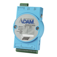
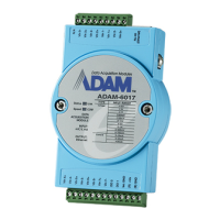
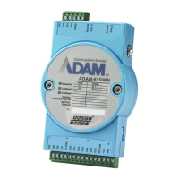
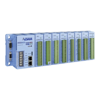
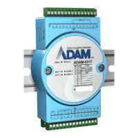
Provides an overview of the ADAM-6300 series remote I/O modules.
Lists the key features and benefits of the ADAM-6300 series modules.
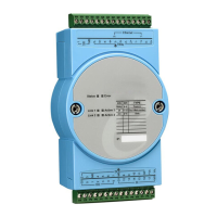
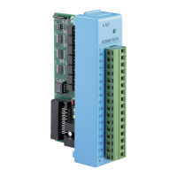
Details the physical components and connections of the ADAM-6300 module.
Explains how to connect the power supply to the ADAM-6300 module.
Describes the Ethernet connection and grounding screw on the module.
Explains the meaning of the status indicators (LEDs) on the ADAM-6300 module.
Provides the physical dimensions of the ADAM-6300 module.
Lists the items included in the ADAM-6300 module package.
Instructions on how to mount the ADAM-6300 module using a DIN rail.
Details the specifications and wiring procedures for the power supply.
Lists general specifications including power, LAN, connectors, and certifications.
Details power reversal protection and operating environmental conditions.
Outlines the specifications for OPC UA protocol support, including sessions and security.
Details Modbus register mapping for ADAM-6350 AI, AO, DI, and DO channels.
Continues Modbus register mapping for ADAM-6350, covering more channels.
Details Modbus register mapping for ADAM-6360D AI, AO, DI, and DO channels.
Details Modbus register mapping for ADAM-6317, covering AI, DI, and DO channels.
Continues Modbus register mapping for ADAM-6317, covering DI and DO channels.
Continues Modbus register mapping for ADAM-6317, covering Analog Input (AI) channels.
Continues Modbus register mapping for ADAM-6317, covering Analog Input (AI) channels.
Details general, digital input, and digital output specifications for the ADAM-6350 module.
Provides diagrams for digital output and digital input wiring for the ADAM-6350.
Illustrates wiring for digital output with resistive and inductive loads.
Lists analog input, digital input, and digital output specifications for the ADAM-6317 module.
Shows the wiring diagram for analog input on the ADAM-6317 module.
Illustrates digital input wiring for the ADAM-6317 module.
Illustrates digital output wiring for the ADAM-6317 module.
Shows examples of "U"(upper) and bottom terminal block configurations.
Details specifications for SSR relay output, digital input, and digital output for ADAM-6360D.
Illustrates wiring for relay output on the ADAM-6360D module.
Illustrates digital input wiring for the ADAM-6360D module.
Shows examples of terminal block configurations for digital output.
Specifies the necessary hardware and software for the host computer.
Guide on downloading and installing the Advantech configuration utility.
Describes the functions available in the Menu Bar of the utility.
Explains the icons and functions on the Toolbar of the utility.
Details the Module Tree and Status Display Areas of the utility.
Lists and explains items under File, Tools, Setup, and Help menus.
Details the function of each icon on the Adam/Apax .NET Utility Toolbar.
Explains the five categories within the Module Tree Display Area.
Describes the main interaction window for configuration and testing.
Details how to view and modify firmware version, device name, and description.
Explains network settings like MAC address, IP address, and default gateway.
Describes how to set and reset the password for security.
Explains how to import firmware files to update the module.
Guides on connecting the module and setting network and I/O types.
Details configuring network settings and selecting I/O types for OPC UA.
Guides on connecting the OPC UA client to the server.
Specifies how to enter the port number for the OPC UA client connection.
Guides on selecting security policies and authorization for OPC UA sessions.
Explains how to connect using a non-security mode for OPC UA.
Covers configuration for analog input channels, including integration time and burnout.
Details configuration for digital input channels, including DI mode and inversion.
Explains how to configure integration time for all analog input channels.
Details how to enable and configure the burnout function for analog inputs.
Explains how to set the burnout value for analog input ranges.
Guides on setting different input ranges for individual analog input channels.
Explains how to view the scaled value of an analog input channel.
Describes how to view the status of an analog input channel.
Introduces the two types of DI channels and their capabilities.
Guides on configuring digital input channels via the OPC UA tab.
Details how to monitor the DI status using the DIValue.
Explains how to enable or disable the signal inversion for digital inputs.
Guides on configuring digital filter settings (enable and width) for digital inputs.
Continues filter width configuration for digital inputs.
Explains how to configure and use the counter mode for digital inputs.
Details counter start, value, and retain functions.
Guides on configuring and monitoring the frequency mode for digital inputs.
Introduces the different DO modes available for digital outputs.
Guides on configuring digital output modes (DO, Pulse Output) via OPC UA.
Details how to select DO, Pulse Output, and Pulse Output Continue modes.
Explains how to set the DO value (on/off) for digital outputs.
Guides on configuring pulse output for finite pulses.
Details pulse width configuration for pulse output.
Guides on setting pulse output count and start for digital outputs.
Explains how to configure pulse start for digital outputs.
Guides on configuring continuous pulse output.
Details pulse width configuration for continuous pulse output.
Guides on setting pulse start for continuous pulse output.
Guides on configuring the SSR relay output mode (on/off).
| Series | ADAM-6300 |
|---|---|
| Category | I/O Systems |
| Power Supply | 10-30 VDC |
| Isolation Voltage | 3000 VDC |
| I/O Type | Analog Input/Output, Digital Input/Output |
| Communication Interface | RS-485, Ethernet |
| Input Channels | Varies by model |
| Output Channels | Varies by model |
| Protocol | Modbus TCP |