ARK-3510 User Manual 10
2.1 Introduction
The following sections show the internal jumpers setting and the external connectors
pin assignment for application.
2.2 Jumpers
2.2.1 Jumper Description
You may configure ARK-3510 to match the needs of your application by setting jump-
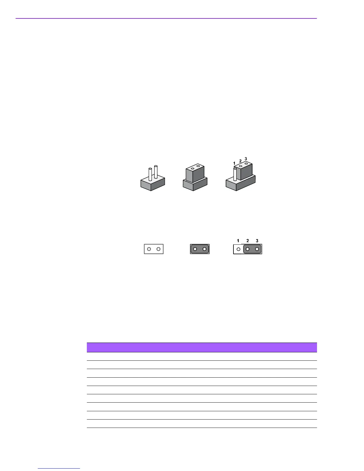
ers. A jumper is a metal bridge used to close an electric circuit. It consists of two
metal pins and a small metal clip (often protected by a plastic cover) that slides over
the pins to connect them. To close a jumper, you connect the pins with the clip. To
open a jumper, you remove the clip. Sometimes a jumper will have three pins,
labeled 1, 2 and 3. In this case you would connect either pins 1 and 2, or 2 and 3.
The jumper settings are schematically depicted in this manual as follows.
A pair of needle-nose pliers may be helpful when working with jumpers. If you have
any doubts about the best hardware configuration for your application, contact your
local distributor or sales representative before you make any changes. Generally, you
simply need a standard cable to make most connections.
2.2.2 Jumper List
Table 2.1: Jumper List of Main Board
J1 DDR3/DDR3L Setting
J2 Auto Power On Setting
J3 COM4 RS232/422/485 Setting
J4 COM3 RS232/422/485 Setting
J5 COM4 RS232/422/485 Setting
J6 COM3 RS232/422/485 Setting
J7 COM4 RS232/422/485 Setting
J8 COM3 RS232/422/485 Setting
J9 Clear CMOS