61
EN
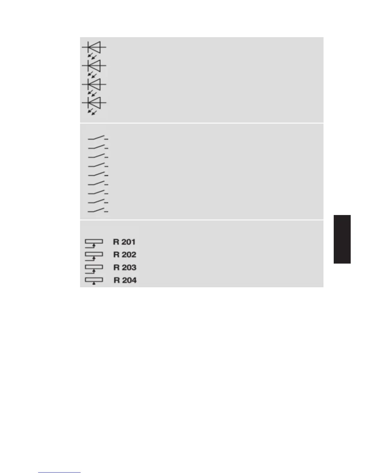
Fig. 2 Operating elements
H 100
LED gn ON
H 101
LED rt PULSE INHIBIT
H 250
LED rt LOAD FAULT
H 350
LED gn
Diagnosis/percent modulation indication
S1.10 Analog output 10V / 20mA Chap. 4.2.4
S1.9 Live Zero analog output
S1.8 Setpoint value input Chap. 4.2.3
S1.7 Setpoint value input
S1.6 Live Zero setpoint Chap. 4.2.3
S1.5 Control mode / Thyro-Tool mode Chap. 4.2.2
S1.4 Control mode / Thyro-Tool mode
S1.3 Control mode / Thyro-Tool mode
S1.2 Operation mode Chap. 4.2.1
S1.1 Operation mode
Phase angle 1st for transformer TRAFO ADAPTION
Chap. 4.3.1
load SCALE SETPOINT Chap. 4.3.3
Control end CURRENT LIMIT Chap. 4.3.4
Current limit SCALE OUTPUT Chap. 4.3.6
Increase Load monitoring LOAD FAULT Chap. 4.3.7