76
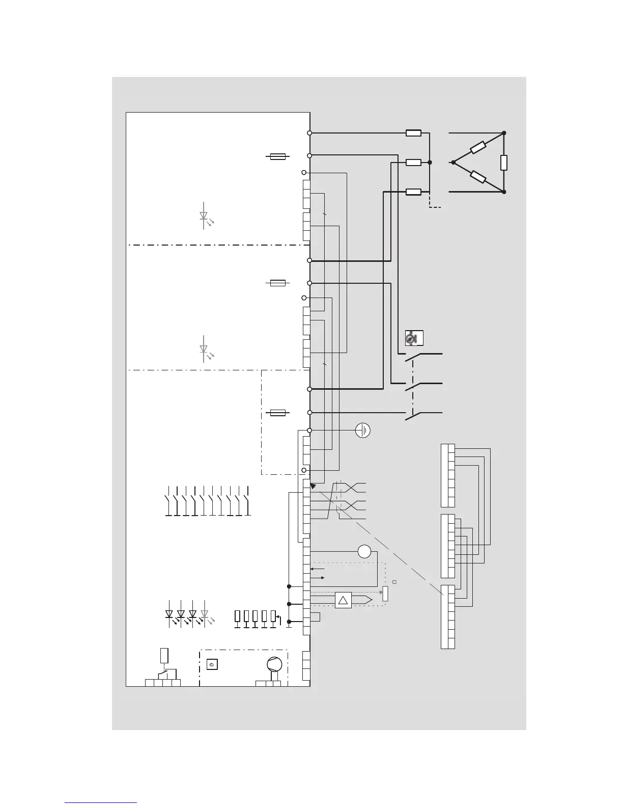
Fig. 9 Connection diagram Thyro-A 3A…H RL1, …H RLP1
5..10 K
3
Mains supply
Rotating field: clockwise
L1 L2 L3
N
R
LoadMaster
Slave 1
Slave 2
X22 2 3 4 5
System X22
6 7 X22 2 3 4 5
System X22
6 7 X22 2 3 4 5
System X22
6 7
*wired ex works
(depending on the
application)
* see chapter "Load connection types"
*
+5V
+
3
fan only for
HF - Types
230V, 50/60Hz
X7 2
3
X1 1 2
signalling
relay
X3 1
2
3
K1
X11 1 2
24V
+ - DC
~ ~ AC
Auxiliary
Voltage-
Supply
X1 1 2
P1/X10
P1/X10
P1/X10
5-72-4X22 X1 1 2 5-72-4X22
U1 U2 W1 W2
Configuration S1.
X22 1 2 3 4 5-7
Connection for bus
module option
Status
PE
Shield / Ground
Pulse inhibit
Setpoint
Sync. Out
Sync. In SYT-9
Pot. supply
mA, V
Analogue Output
X2 1 2 3 4 5 6 7 8 9 10
+
V1 V2
R 205
R 204
R 203
R 202
R 201 Trafo Adaption
Scale Setpoint
Current Limit
Scale Output
Load Fault
Analog.-Output 10V/20mA
Operating Mode / Load description
Analog.-Output Life Zero
Set Point Input
Set Point Input
Set Point Live Zero
Control Mode / Thyro-Tool
Control Mode / Thyro-Tool
Control Mode / Thyro-Tool
Operating Mode / Load description
10
9
8
7
6
5
4
3
2
1
H 101
H 100
Pulse Inhibit
Power On
H 350 Diagnose (Intern)
H 250 Load Fault
Parameter
H 350 Diagnose (Intern) H 350 Diagnose (Intern)
F1
Semi-
conductor-
Fuse
F1
Semi-
conductor-
Fuse
F1
Semi-
conductor-
Fuse
for UL-applications refer to Technical
Data, Connector Data (power circuit)
Use shielded
control lines!
Load
Master 2 evalS1 evalS
*wired ex works
Thyro-A
3A ... H(F) RL1 / RLP