AM Series Boiler Heat Exchanger Maintenance & Replacement
Technical Instruction Document
Installing the Larger Wiring Harness
NOTE
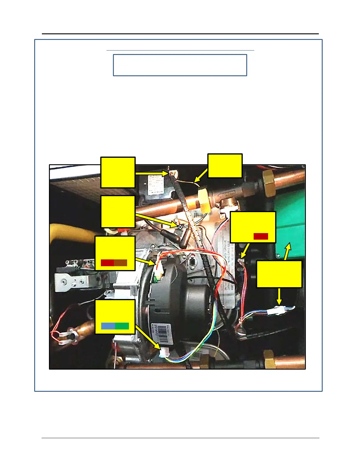
Refer to Figure 5-7 for steps 5 through 10.
5. Connect the fan connector (with red and orange wires) to the upper fan connector.
6. Connect the fan connector (with blue and green wires) to the lower fan connector.
7. Connect the two pin connector (with red wires) to the flue sensor fuse connector (red).
8. Connect the igniter power cable to the upper igniter.
9. Connect the igniter power cable ground wire tab to the screw on the burner flange, just
above the igniter cables.
10. Plug in the motorized valve.
Figure 5-7: Larger Harness – Right Side Cable Connections
IGNITER
POWER
STEP 9:
IGNITER
GROUND
GROUND
FLUE
SENSOR
STEP 5:
UPPER
FAN CONN.
(RED/ORG)
STEP 6:
LOW ER
FAN CONN.
(BLU/GRN)
STEP 10:
MOTORIZED
VALVE
TID-0132_99 AERCO International, Inc. • 100 Oritani Dr. • Blauvelt, NY 10913 Page 32 of 36
Ph.: 800-526-0288 01/18/2015
 Loading...