06/05/13 AERCO International, Inc. • 100 Oritani Dr. • Blauvelt, NY 10913 • Ph: 800-526- 0288 Page 27 of 112
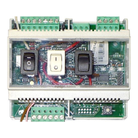
Modulex E8 Controller and BCM
Operations and Maintenance Manual
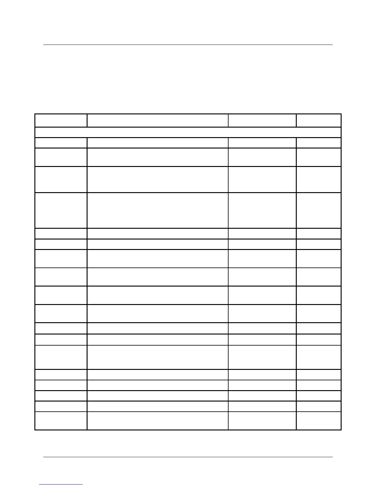
NOTE
Whenever “CODE NO.” is displayed, it indicates that the valid
password must be entered. This is accomplished by entering code
0000 (four zeros) by pressing the Program Key four (4) times.
Table 4-3: EXPERT Menu Listing
FUNCTION DESCRIPTION ENTRY RANGE DEFAULT
Permits entry of valid Code No.(0000)
BUS ID HS
BUS ID HS MUST be set to - - - - to operate
01 - 08
DO NOT
BUS ID 1
The heating circuits are sequentially
numbered starting with “01“, heating circuit
numbers must not be assigned twice.
(00), 01 – 15 01
BUS ID 2
Heating circuits are sequentially numbered
starting with “01“, heating circuit numbers
must not be assigned twice.
(00), 01 – 15 - - - -
Outdoor sensor power supply
Bus terminating resistor (Must be set to 01)
EBUS
Switches the Ebus supply ON/OFF 00, 01 (OFF/ON) 01 (ON)
TIME
Not Applicable
MAX T-COLL
Sets the maximum allowable header set
86.0°F – 230.0°F 185.0°F
MIN T-COLL
Sets the minimum allowable header set point
50.0°F – 176.0°F 50.0°F
V-CURVE
0 to 10 Volt input Voltage curves. Choose
from preset curves (see Section 4.4.1) or
00 – 11 11
Minimum set point temperature
Maximum set point temperature
CURVE 11-UO
Stop/Start voltage level. Going below/above
this setting will stop/start the Boiler.
0.00V – 10.00V 1.00