06/05/13 AERCO International, Inc. • 100 Oritani Dr. • Blauvelt, NY 10913 • Ph: 800-526- 0288 Page 74 of 112
Modulex E8 Controller and BCM
Operations and Maintenance Manual
7.7 Modbus Software Set-Up
The following paragraphs provide the information and procedures necessary to configure the
Boiler Communications Modules (BCMs) to operate on a Modbus Network.
NOTE
The following paragraphs assume that between 1 and 9 Modulex
Boilers are being controlled on the Modbus Network.
7.7.1 BCM Set-Up for Modbus Operation
The BCM Controller can be set up for the following types of Modbus operating modes:
• Monitoring and Configuration Only
• AERCO BMS II/ACS Modbus Control and Monitoring
• Modbus Remote Setpoint Control and Monitoring
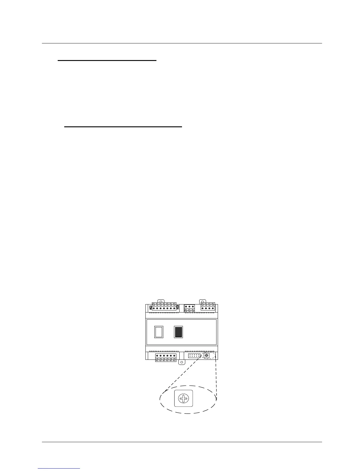
In order for the BCM Controller to be recognized by the Modbus Master, a valid address must
be set at each BCM on the Modbus Network. Address selection on each BCM is accomplished
by setting rotary DIP switch SW1. This switch is located in the lower right portion of each BCM
as shown in Figure 7-12.
As Figure 7-12 shows, SW1 is a 10-position switch labeled 0 – 9. SW1 is set to the desired
position using a small flat-tip screwdriver. Figure 7-12 shows SW1 set to address 0 (zero) which
disables the BCM on the Modbus Network. Only Modbus addresses 1 through 9 will be
recognized by the Modbus Master. SW1 must be set to a different position for each Modulex
Boiler being controlled on the Modbus Network.
Once the desired address has been set on each BCM, the Modulex Boiler is configured for
Modbus Network control by the controlling Master EMS/BAS or AERCO BMS II/ACS. In order
for the BCM to act as the Back-Up Controller if the Modbus Master signal is lost, the
ENABLE/DISABLE switch must be set to ENABLE (1).
See Section 9 of this document and Section 2 of GF-124 for Modbus points for the BCM and
BMS II/ACS.
Y2
Y3
Y4
Y1
SW
1
A1
I
0
0
2
1
4
3
5
6
7
8
9
SW1
Figure 7-12: Location of BCM Address Selection Switch SW1