PR1: 02/23/12 Page 58 of 112
AERCO International, Inc. • 100 Oritani Dr. • Blauvelt, NY 10913 • Ph: 800-526- 0288
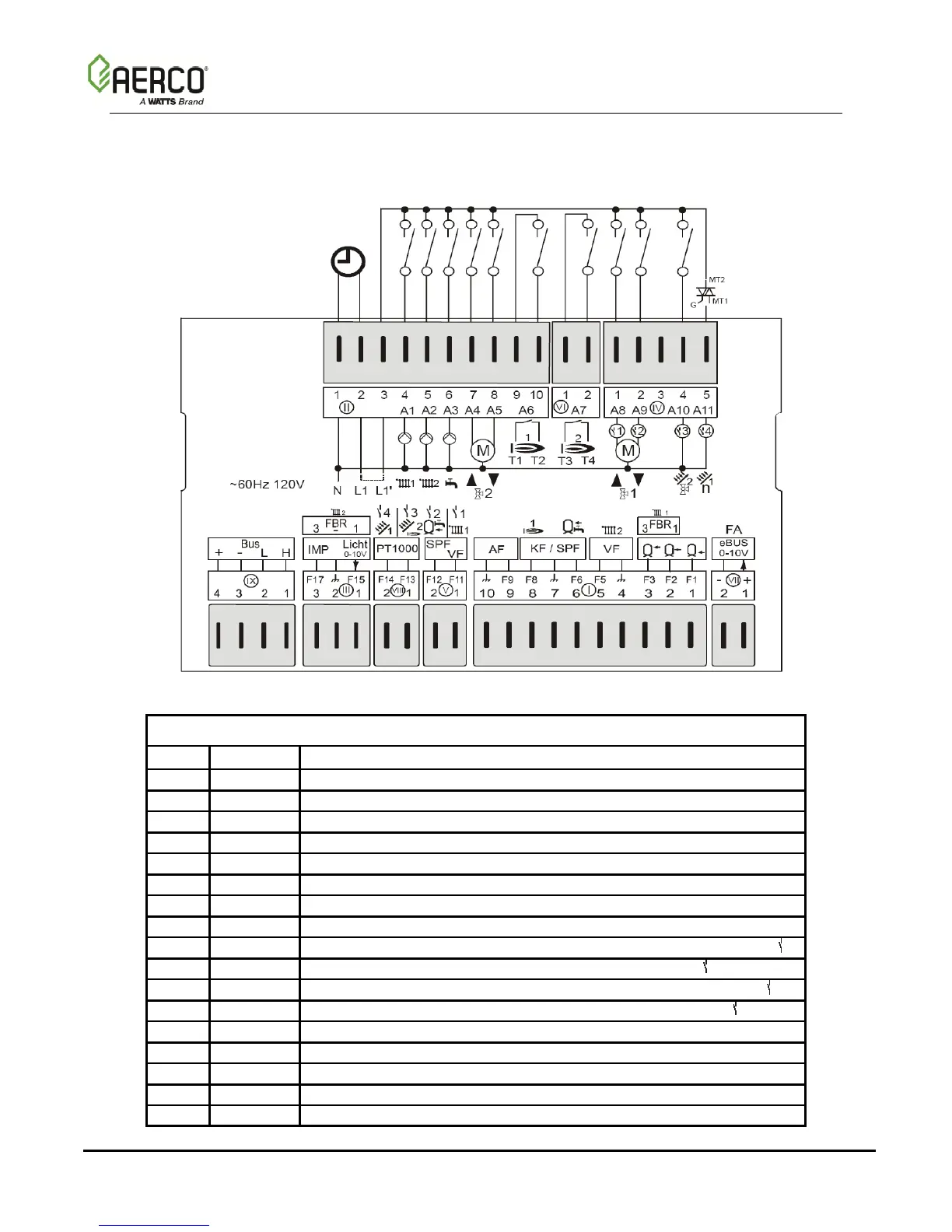
6. CONNECTION DIAGRAMS
120V∼; Relay switching capacity 2(2)A, 250V∼
Sensor Terminal Assignments
Ebus (FA) or 0-10V output
F1/F2/F3 = buffer storage tank low/middle/top
FBR2 (FBR1) for heating circuit 1
F2 = Room sensor for heating circuit 1
F5 = Flow sensor heating circuit 2
F8 = Boiler sensor/header sensor
F11 = Flow sensor heating circuit 1/Multifunction relay sensor 1
F12 = Hot-water tank low/Multifunction relay sensor 2
F13 = PT1000 => HS2/collector 2/Multifunction relay sensor 3
F14 = PT1000 => Collector 1/Multifunction relay sensor 4
FBR2 (FBR1) for heating circuit 2
F15 = 0-10V input/light sensor/Room sensor for heating circuit 2
F17 = Pulse counter for output measurement