06/05/13 AERCO International, Inc. • 100 Oritani Dr. • Blauvelt, NY 10913 • Ph: 800-526- 0288 Page 70 of 112
Modulex E8 Controller and BCM
Operations and Maintenance Manual
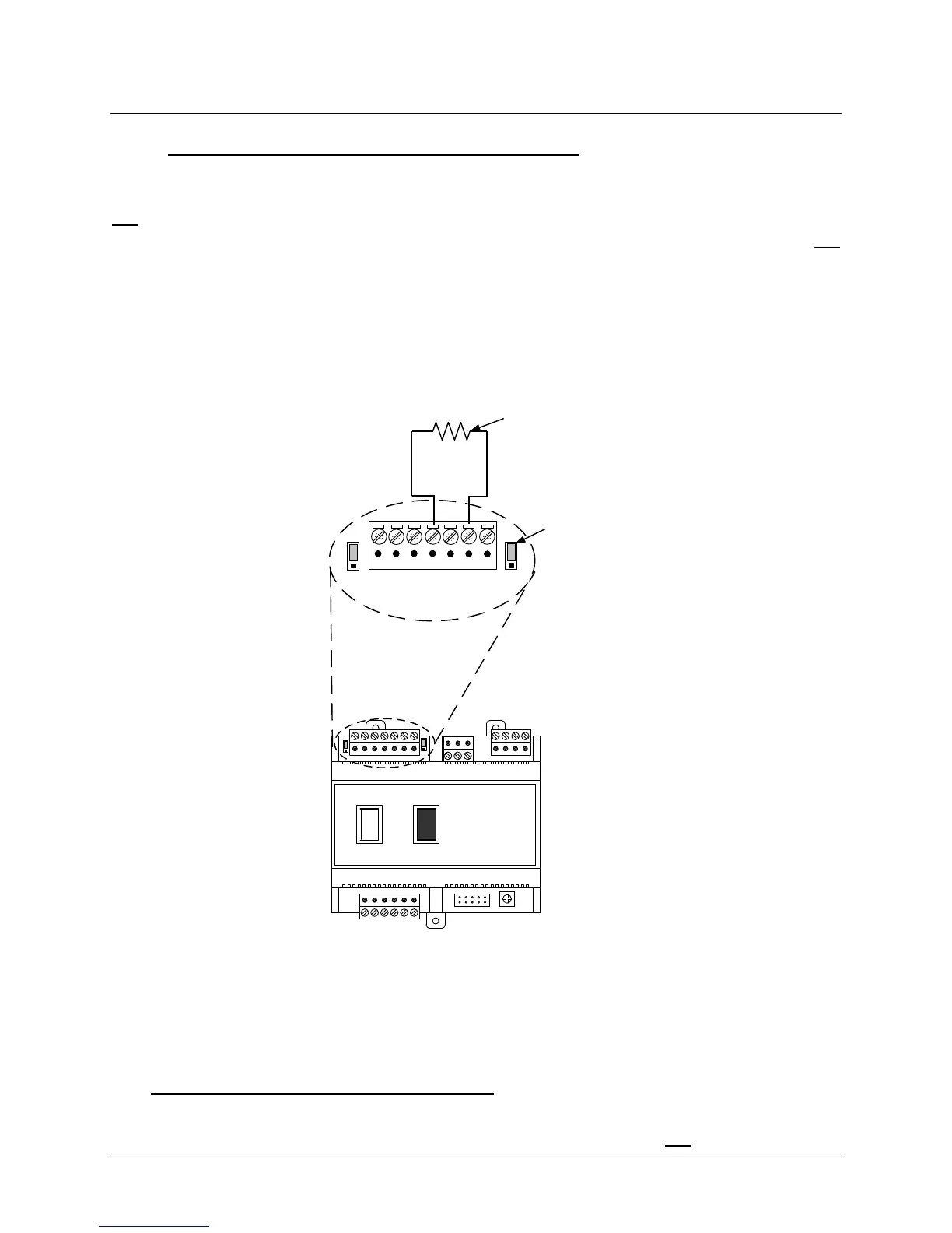
7.5.2 BCM Controller Terminating Resistor and Bias
BCMs can function only as Slave devices on a Modbus Network. Since the Slaves are
connected in a “Daisy-Chain” configuration, the terminating resistor must be enabled only in the
last BCM Controller in the chain. Enabling the terminating resistor is accomplished by
positioning jumper JP1 as shown in Figure 7-9 only on the BCM Board contained in the last
BCM Controller.
As mentioned in paragraph 7.5.1, when the controlling Master is an EMS or BAS, pull-down
bias may be implemented by connecting a 1K ohm resistor as shown in Figure 7-9. DO NOT
install this bias resistor if the controlling Master is an AERCO BMS II or ACS. Bias will be
provided by the BMS II/ACS DIP switches. The last unit in the chain must be energized (even if
disabled) to enable bias.
Y2
Y3
Y4
Y1
SW1
A1
I
0
BCM FRONT VIEW
7 6 5 4 3 2 1
Y2
JP2
JP1
T
C
V
JUMPER
SHOWN IN
“TERMINATED”
POSITION
1K OHMS
PULL-DOWN
BIAS
RESISTOR
DO NOT
INSTALL BIAS
RESISTOR
WHEN BMS II
IS “MASTER”
Figure 7-9: BCM Loop Termination and Bias
7.6 Modbus Network Wiring Diagram
A “Sample” Modbus Network wiring diagram for an AERCO BMS II/ACS Master controlling BCM
Slaves is shown in Figure 7-10. Activate the terminating resistor in the last BCM on the daisy-