06/05/13 AERCO International, Inc. • 100 Oritani Dr. • Blauvelt, NY 10913 • Ph: 800-526- 0288 Page 52 of 112
Modulex E8 Controller and BCM
Operations and Maintenance Manual
5.3.5 Viewing the Set Point
The set point is displayed as shown in instructions below.
NOTE
When viewing the set point temperature using the steps in
paragraph 5.3.5, you will note that the when the voltage source is
equal to 0.9 Volt, the set point temperature will drop to 41°F (9°C),
thereby shutting down the boiler.
Example:
U1 = 1 Volt and the set point = 80°F
U2 = 8 Volts and the set point = 180°F
UO should be set to 0.9 Volt
Viewing the Setpoint
1. Turn the Rotary Knob to the DISPLAY menu – INSTALLATION sub-menu.
2. Press the Program Key to enter the INSTALLATION sub-menu.
3. Using the Rotary Knob, scroll to T-EXT DES to view the set point temperature.
5.4 Domestic Hot Water Operation Using A Tank Sensor
With the controller hinged panel closed, turn the Rotary Knob until the Faucet symbol ( )
appears in the lower part of the display window. When there is a demand for domestic hot
water (DHW), a second Faucet symbol will be displayed. This second Faucet symbol indicates
that the boiler is currently in the DHW mode and is raising the temperature of the domestic
water to the DHW set point. Once the DHW demand has been satisfied, the boiler will switch
back to the space heating mode. The second Faucet symbol will change to a heating circuit
symbol, indicating that the boiler is back in the space heating mode.
The following procedures describe the wiring connection and Controller configuration setting
needed to provide domestic hot water (DHW) using a tank sensor installed in a thermowell.
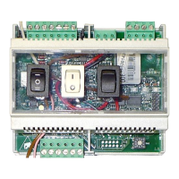
5.4.1 Sensor Wiring Connections
To monitor the DHW temperature, connect the tank sensor wire leads to Connector 1,
Terminals 6 (F6) and 7 (GND) on the rear of the Controller. After the sensor is connected, turn
the ON/OFF switch to the OFF position, then back to the ON position. This is necessary to
ensure that the Controller recognizes the added sensor.