06/05/13 AERCO International, Inc. • 100 Oritani Dr. • Blauvelt, NY 10913 • Ph: 800-526- 0288 Page 56 of 112
Modulex E8 Controller and BCM
Operations and Maintenance Manual
5.5 DHW Operation Using an Aquastat
Operation, wiring connections and Controller configuration settings for DHW heating using an
aquastat are virtually identical to the procedures previously described in paragraph 5.4 for the
tank sensor. Therefore, the following paragraphs describe only the differences between these
two types of applications.
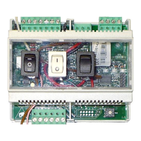
5.5.1 Sensor Wiring Connections
To monitor the DHW temperature, connect the aquastat wire leads to Connector KF/SPF,
Terminals 6 (F6) and 7 (GND). After the sensor is connected, turn the ON/OFF switch to the
OFF position, then back to the ON position. This is necessary to ensure that the Controller
recognizes the added sensor.
IMPORTANT
The aquastat MUST be connected as described above, prior to
configuring the Controller for DHW operation. Also, the aquastat
must be closed (shorted) for the Controller to display the required
sub-menu functions.
5.5.2 Configuring the Controller for DHW With an Aquastat
The procedures for configuring the Controller for DHW with an Aquastat are virtually identical
to those specified in paragraph 5.4.2. The only difference is that the THERM INPUT in the
EXPERT menu/HOT WATER sub-menu must be set to 01 (Aquastat) instead of 00 (Sensor).
5.5.3 Setting the DHW Set Point
Same as paragraph 5.4.3.
5.5.4 Displaying Temperatures Associated With DHW
Same as paragraphs 5.4.4 through 5.4.4.2.
5.6 Boiler & Pump Enable/Disable
The Enable/Disable feature found between terminals 3 and 4 of connector “I” can be used to
start/stop the boiler only in Indoor/Outdoor Reset and Constant Set Point modes of operation.
The Enable/Disable does not start/stop the boiler in 0 to 10 Volt Remote Set Point mode. To
start/stop the boiler in 0 to 10 Volt Remote Set Point mode, see paragraph 5.3.4.
To use the Enable/Disable feature, wire a dry set of contacts between terminals 3 and 4 of
Connector “I” and then set the boiler to Standby mode ( ). To set the boiler to Standby
mode, close the swing-down front panel door of the E8 and turn the wheel counterclockwise
until the Standby symbol ( ) is displayed. With terminals 3 and 4 closed, the Standby
symbol, and others in the display, will be blinking. This indicates that the boiler is enabled.
When the connection is broken between terminals 3 and 4, the Standby symbol, and others in
the display, will stop blinking indicating that the boiler is disabled.
The Enable/Disable feature not only start/stops the boiler but also start/stops the pumps.