06/05/13 AERCO International, Inc. • 100 Oritani Dr. • Blauvelt, NY 10913 • Ph: 800-526- 0288 Page 37 of 112
Modulex E8 Controller and BCM
Operations and Maintenance Manual
F12
Hot water temperature lower or temperature
F13
Solid fuel boiler temperature or collector 2 or
temperature multifunction 3
F14
Collector 1 temperature or temperature
F15; Light; 0-10V I
Room temperature heating circuit 2 or measured
value of the light sensor or voltage value 0-10V
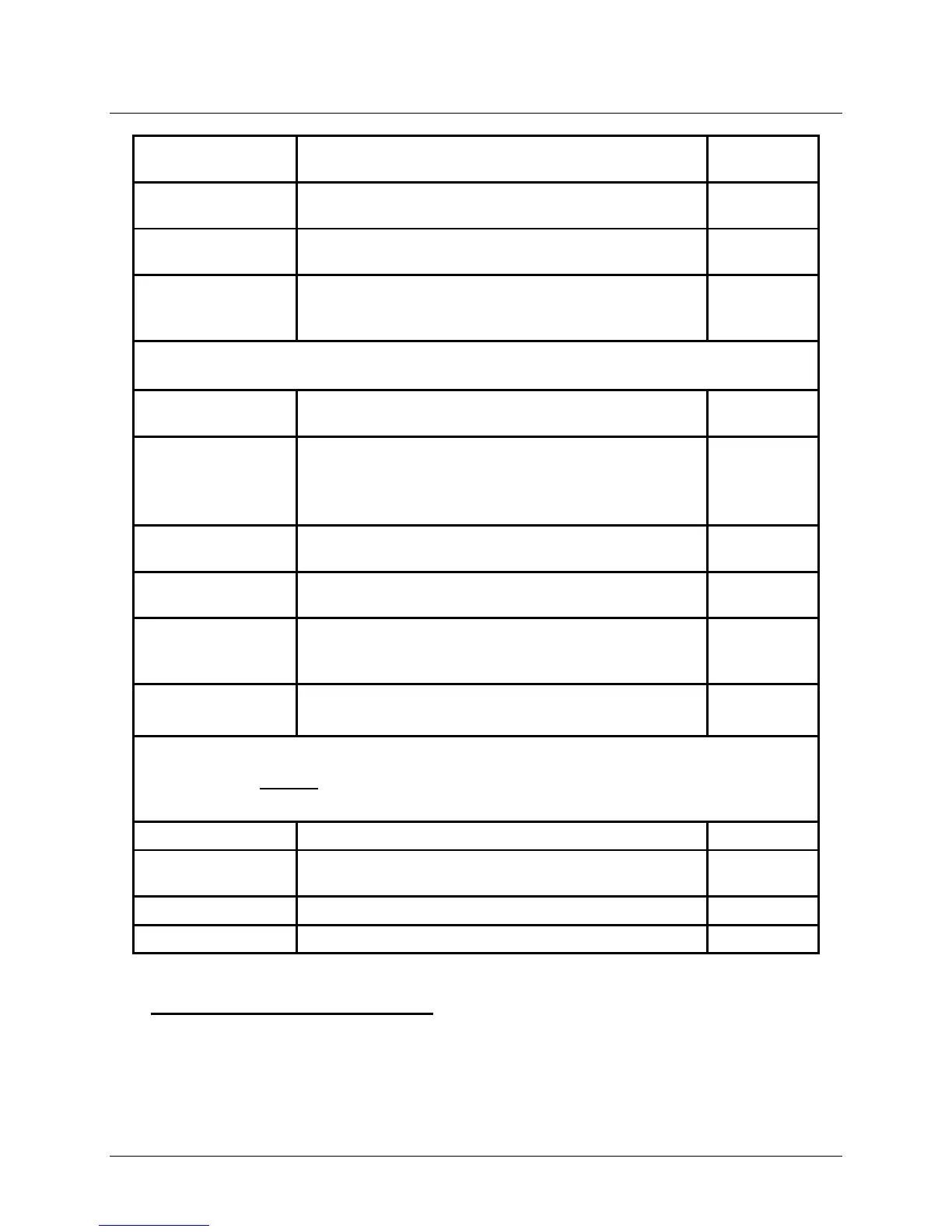
Additional items and functions in the SERVICE Sub-Menu include the following:
SW NO XXX-XX
Specifies the Software Version and Index number
currently installed in the Controller
CASCADE MANU
(1-8)
Starting different burner stages of the cascade
See GF-115-H, Section 7, Sub-section 7.5 for
additional startup instructions using these sub-
BURNER TIME (1-
Program Key – Burner time for all stages
BURNER START
Program Key – Burner start for all stages
LIMITER TEST
(1-8)
Safety temperature limiter test with heat generator
temperature display
Start with Program Key (hold down)!
SERVICE
Input of date or operating hours for service
messages
WARNING: NEVER ATTEMPT TO USE THE FOLLOWING RESET FUNCTIONS.
RESET USER 00
RESET EXPERT
DO NOT USE
RESET T-PRG 00
RETURN
Exit level using Program Key
4.7 E8 Controller Initial Startup
Initial startup of the Modulex Controller requires a number of one-time entries to be made in
the initial INSTALLATION Menu that appears in the display when the E8 controller door is first
opened. Table 4-7 on the next page lists the description, entry range, and default entry for all
parameter. Instructions for entry into this menu is shown below.