06/05/13 AERCO International, Inc. • 100 Oritani Dr. • Blauvelt, NY 10913 • Ph: 800-526- 0288 Page 36 of 112
Modulex E8 Controller and BCM
Operations and Maintenance Manual
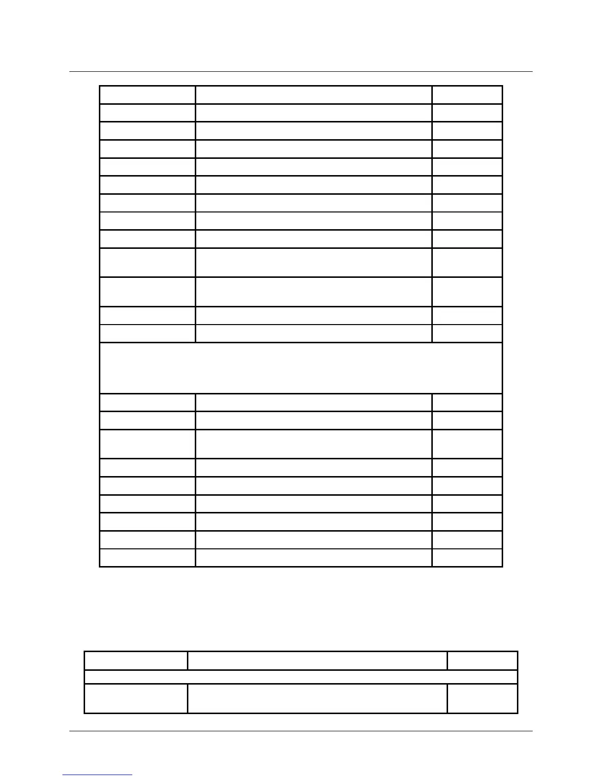
RELAY NO.
00
No relay
01
A1: Pump, Heating Circuit 1
02
A2: Pump, Heating Circuit 2
03
A3: Hot Water Charging Pump
04
A4: Mixer OPEN, Heating Circuit 2
05
A5: Mixer CLOSED, Heating Circuit 2
06
A6: HS 1 ON
07
A7: HS2 ON [2-stage:HS 1+2 (after 10s) ON]
08 A8: Mixer OPEN Heating Circuit 1 /
09
A9: Mixer CLOSED Heating Circuit 1 /
10
A10: Multifunction 3
11
A11: Collector Pump / Multifunction 4
This Sub-Menu is used to check and display the temperature readings of the
sensors connected to the Controller.
F1
Lower buffer storage temperature
F2
Middle buffer storage temperature or room
temperature heating circuit 1
F3
Upper buffer storage temperature
F5
Flow temperature, heating circuit 2
F5
Flow temperature, heating circuit 2
F6
Upper hot water temperature
F8
Heat generator /header temperature
F9
Table 4-6: SERVICE Menu Listing (Continued)
F11
Flow temperature heating circuit 1 or temperature