06/05/13 AERCO International, Inc. • 100 Oritani Dr. • Blauvelt, NY 10913 • Ph: 800-526- 0288 Page 63 of 112
Modulex E8 Controller and BCM
Operations and Maintenance Manual
the E8 and BCM Controllers. Refer to paragraph 7.4.3 for details.
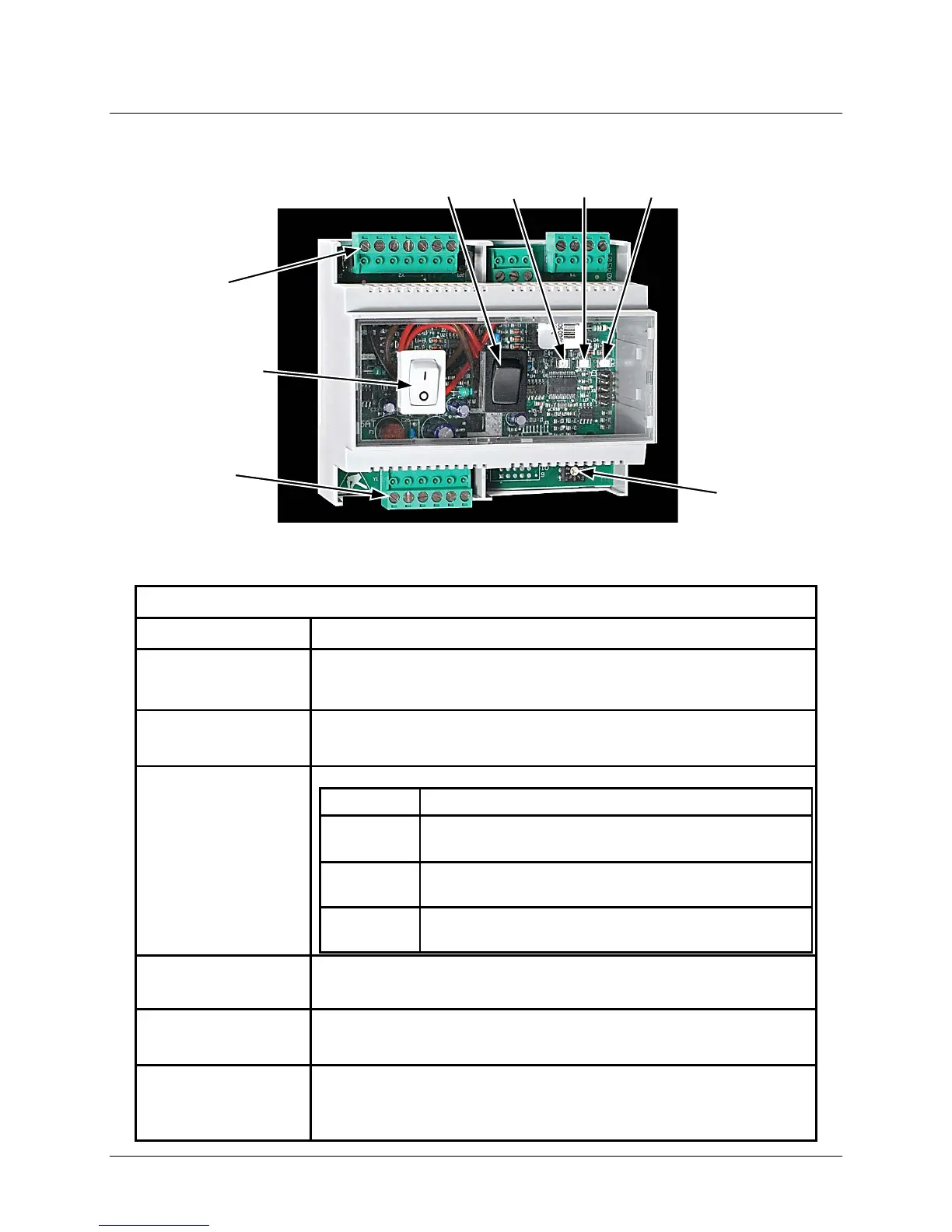
Figure 7-2: Boiler Communications Module (BCM) Features
Boiler Communications Module (BCM) Features and Functions
Feature Function
Enable/Disable
Switch (I/0)
Two-position rocker switch enables the BCM to act as a Back-
Up Controller when placed in the ON (I) position.
Reset Switch
Momentary two-position rocker switch resets (clears) fault relay
and LED when activated.
DL1 LED
(Yellow)
Communication Status Indicator functions as follows:
OFF
No devices detected by either communication
interface.
BLINKING
Only one communication device detected at one
communication interface (input or output).
ON
Both communication interfaces
(input & output) are active.
DL2 LED
(Red)
Alarm Status LED lights when a fault is detected by the BCM.
Activating the Reset Switch will clear the faults.
DL3 LED
(Green)
Pump Status Indicator lights when Pump is running.
SW1
10-Pos. Rotary
Switch
Screwdriver-adjustable rotary switch labeled 0 – 9. This switch
is used to set the corresponding address of the Modulex Boiler
on the input Modbus or Ebus Network.
Communications
Communications
(Ebus)
Enable/Disable
Switch (I/O)