06/05/13 AERCO International, Inc. • 100 Oritani Dr. • Blauvelt, NY 10913 • Ph: 800-526- 0288 Page 91 of 112
Modulex E8 Controller and BCM
Operations and Maintenance Manual
Some of the functions in this sub-menu require a valid Code No. (password) to be entered,
prior to accessing/changing Function values. When prompted by a “CODE NO.” display, enter
0000 (four zeros) by pressing the Program Key four times. This will allow function access.
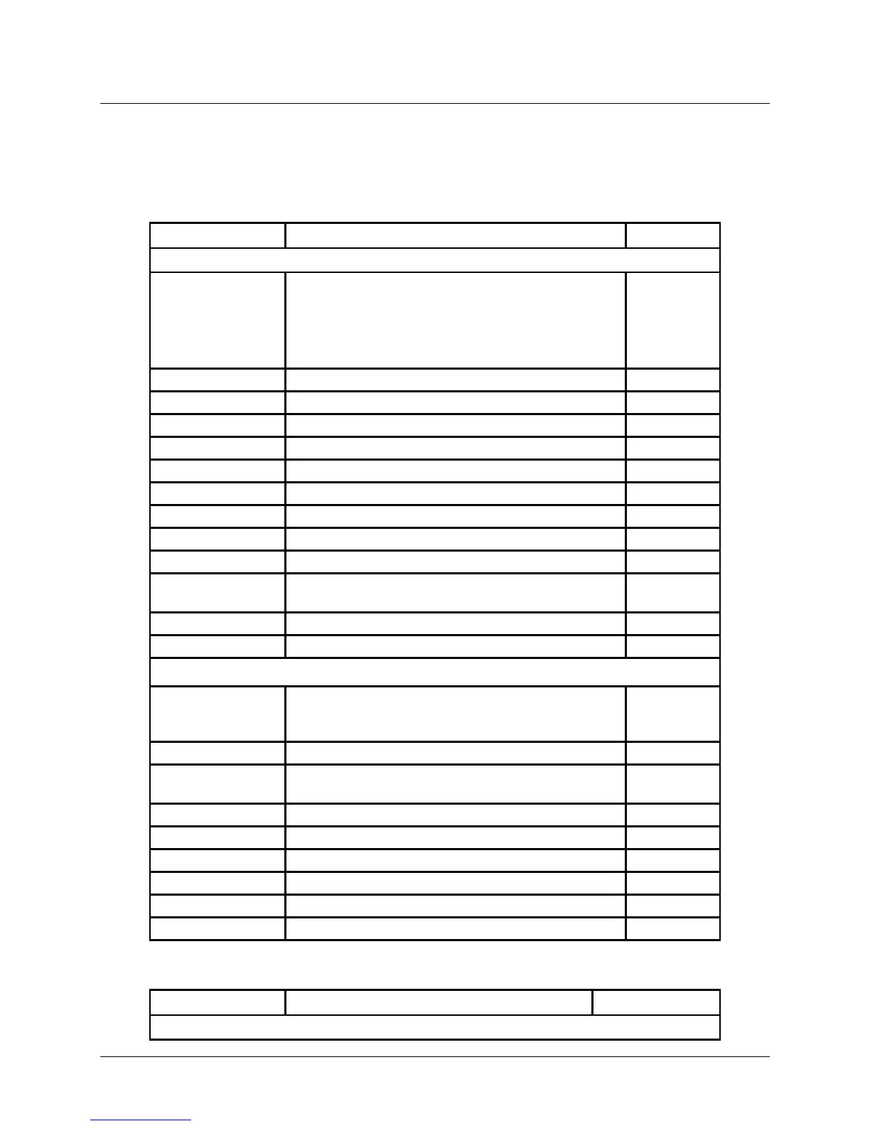
Table 8-6: GENERAL Menu / SERVICE Sub-Menus and Parameters
RELAY NO.
This Sub-Menu is used to check the status of
the relays contained in the Controlller. These
relays are numbered 00 through 11 and are
defined as shown below. CODE NO. Entry is
required to access these relays.
A1: Pump, Heating Circuit 1
A2: Pump, Heating Circuit 2
A3: Hot Water Charging Pump
A4: Mixer OPEN, Heating Circuit 2
A5: Mixer CLOSED, Heating Circuit 2
A7: HS2 ON [2-stage:HS 1+2 (after 10s) ON]
A8: Mixer OPEN Heating Circuit 1 / Multifunction 1
09
A9: Mixer CLOSED Heating Circuit 1 / Multifunction
A11: Collector Pump / Multifunction 4
SENSOR TEST Sub-Menu
This Sub-Menu is used to check and display the
temperature readings of the sensors connected to
F1 Buffer storage temperature Lower
F2
Buffer storage temperature middle or
room temperature heating circuit 1
Upper buffer storage temperature
Flow temperature, heating circuit 2
Flow temperature, heating circuit 2
Upper hot water temperature
Heat generator /header temperature
Table 8-6: GENERAL Menu / SERVICE Sub-Menus and Parameters (Continued)