MODULEX EXT 321, 481, 641, 802, 962, 1123 BOILERS
Installation, Operation & Maintenance Manual
OMM-0087_0F AERCO International, Inc. • 100 Oritani Dr. • Blauvelt, NY 10913 Page 133 of 146
GF-143 Phone: 800-526-0288 07/13/15
Disassembling the Boiler for Maintenance – Continued
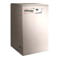
Figure 7-18: Unscrewing Lift Screw into Tab Hole (Step 14)
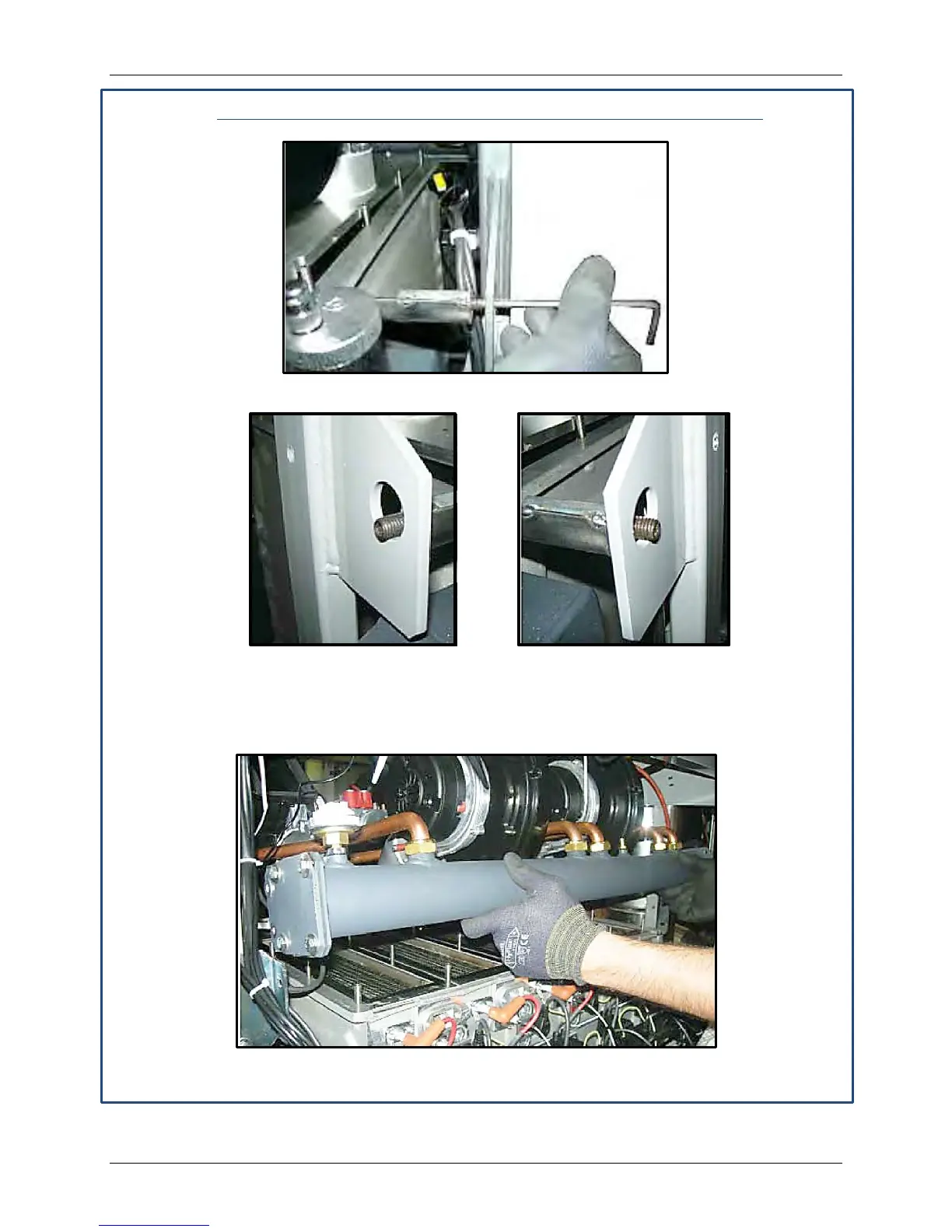
Figure 7-19: Lift Screws Extended into Tab Holes, Left and Right Sides (Step 14)
14. Refer to Figure 7-20, then lift up the front of the burner assembly and raise up until the two
lift pins can be inserted (Figure 7-22) at the left and right sides in order to hold up the burner
assembly.
Figure 7-20: Lifting Burner Assembly from Front (Step 15)