MODULEX EXT 321, 481, 641, 802, 962, 1123 BOILERS
Installation, Operation & Maintenance Manual
OMM-0087_0F AERCO International, Inc. • 100 Oritani Dr. • Blauvelt, NY 10913 Page 39 of 146
GF-143 Phone: 800-526-0288 07/13/15
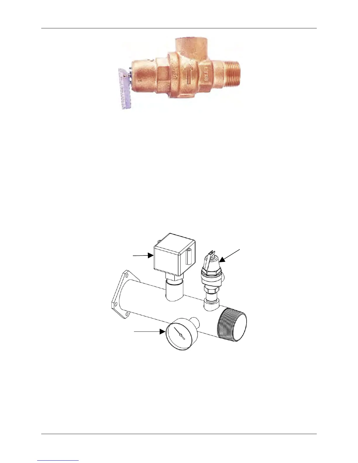
Figure 3-15: Pressure Relief Valve
3.12 CSD-1 Manifold Assembly (Supplied)
The installation of a flow switch, pressure/temperature gauge, and an ASME compliant safety
pressure relief valve designed for the boiler output capacity are required. These major
components are supplied with the boiler and must be assembled and wired when installing the
boiler at the site. The manifold assembly components supplied are:
• 3/4” Pressure Relief Valve (Figure 3-15)
• Flow Switch
• Pressure/Temperature Gauge
The pressure relief valve and other manifold components are shown in Figure 3-16.
Figure 3-16: Manifold Assembly and Components
To install the pressure relief valve and the other components shown, proceed as shown in
instructions below.
NOTE
Use Teflon tape or a suitable pipe joint compound for component
and piping connections described in the following steps. Refer to
Figure 5 for component identification.
Pressure/Temperature
Gauge
Valve