MODULEX EXT 321, 481, 641, 802, 962, 1123 BOILERS
Installation, Operation & Maintenance Manual
Page 88 of 146 AERCO International, Inc. • 100 Oritani Dr. • Blauvelt, NY 10913 OMM-0087_0F
07/13/15 Phone: 800-526-0288 GF-143
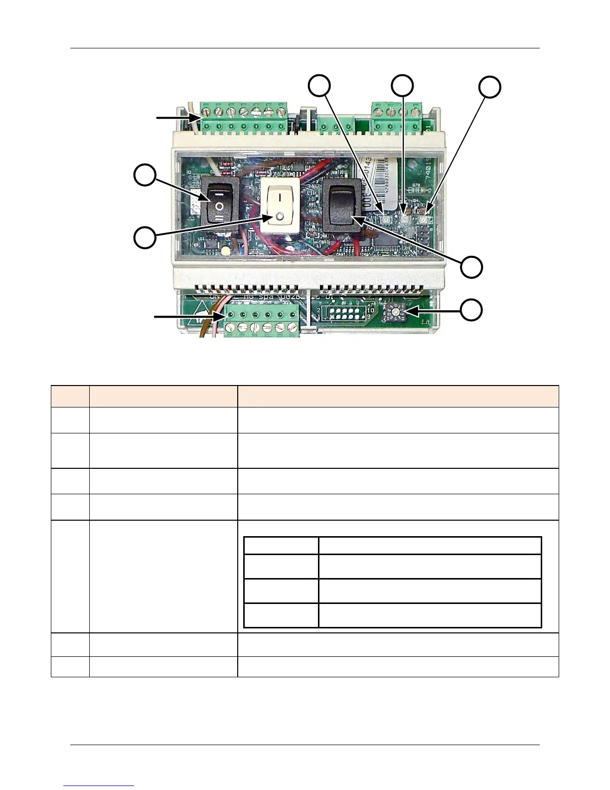
Figure 4-6: BCM (Boiler Control Module) Features
Table 4-5: BCM (Boiler Control Module) Features and Functions
Item
Feature Function
A
Change-Over Series/Parallel,
3-Position Switch
Three-position rocker switch for setting internal/external boiler control.
B
Enable/Disable (I/0),
2-Position Switch
Two-position rocker switch enables the BCM to act as a Back-Up
Controller when placed in the ON (I) position. See Table 4-
6 for
description of settings related to Item B switch.
C
Reset Switch
Momentary two-position rocker switch resets (clears) fault relay and
D
SW1,
10-Position Rotary Switch
Rotary switch labeled 0 – 9. Sets the corresponding address of Boiler
on the input Modbus or EBUS Network.
E
DL1 LED: (YELLOW)
Communication Status Indicator functions as follows:
Status Description
OFF
No devices detected by either communication
interface.
BLINKING
Only one communication device detected at
one communication interface (input or output).
ON
Both communication interfaces
(input & output) are active.
F
DL2 LED: (RED)
Alarm Status LED lights when a fault is detected by the BCM.
Activating the Reset Switch will clear the faults.
DL3 LED: (GREEN)
Pump Status Indicator lights when Pump is running.
Communications
Connector
(Modbus/Ebus)
Communications
Connector (Ebus)
Enable/Disable
2-Pos. Switch
Change-Over
3-Pos. Switch
C
D
E
F