:Anapurna M4F - Operator Manual Stay ahead. With Agfa Global Services.
36 Operations - Changing the parameters
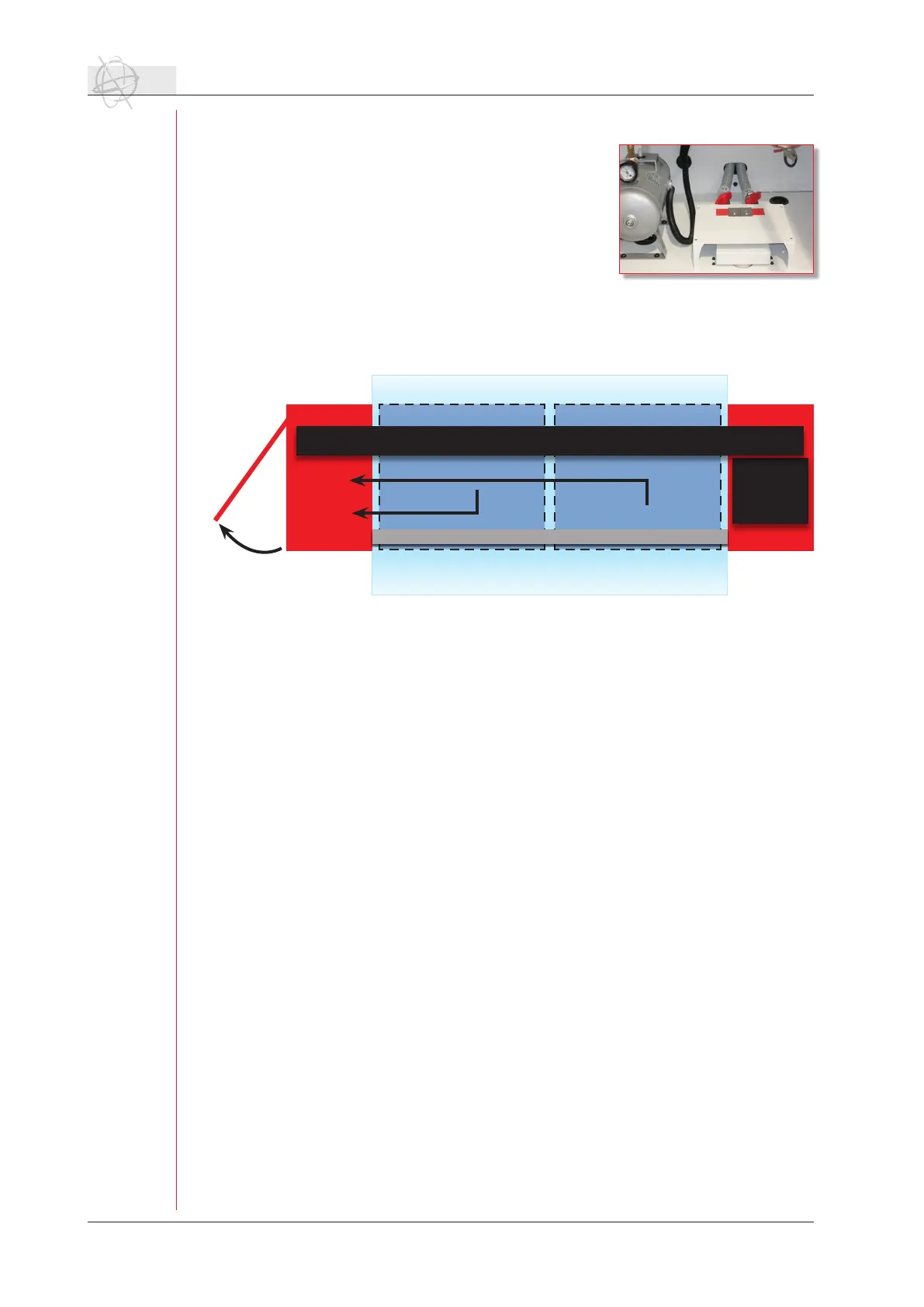
c. Vacuum system.
The vacuum table of the :Anapurna M4F is divided
in two equal parts. Each part of the table gets the
vacuum from an independently controlled valve. The
vacuum pump (ring blower) is controlled by a single
switch (front or rear side) but the output can be con-
trolled by two seperate valves. These valves are po-
sitioned underneath the capping station; access is
through the side door. Valve 1 controls the part of
the table at the right side (home position), valve 2 is
connected to the left side (purge position).
Depending on the position and size of the media, the vacuum can be controlled
through these valves.
If the media only covers one of the two parts of the vacuum table, e.g. vacuum 1,
the suction underneath your media can be increased by closing the valve of the
unused part of the table.
conveyor belt
shuttle
HomeCapping
top view :Anapurna M4F
registration bar
Vacuum 1
Vacuum 2
Valve 1
Valve 2