1200 Series Quarternary Pump User Manual 35
Installing the Pump
3
Optimizing the Stack Configuration
1 Analog signal to recorder, for PN see “Cable Overview” on page 120
2 CAN Bus cable for inter module communications
5181-1561 (0,5m)
5161-1519 (1,0m)
3 CAN Bus cable to handheld controller
4 Remoter cable
5061-3378
Pressure output to recorder, for PN see “Cable Overview” on page 120
5AC power
6 GPIB or LAN to control software, for PN see “Cable Overview” on page 120
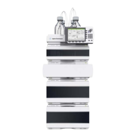
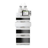
If a single stack configuration becomes too high, e.g. if an additional module like a G1327A
ALS Thermostat is added or if your bench is to high, a two stack configuration may be a
better setup. Separate the stack between pump and autosampler and place the stack
containing the pump on the right side of the stack containing the autosampler.
 Loading...


