Burst Modulation In burst modulation, the function generator turns
the carrier wave output “on” and “off ” in a controlled manner. The
carrier output can be controlled using either triggered or externally-
gated methods.
When configured for triggered operation, the function generator can
output a carrier waveform with a user-specified number of complete
cycles. Each time a trigger is received, the specified number of complete
cycles is output. You can also specify a starting waveform phase in
triggered operation. Zero degrees is defined as the first data point in
waveform memory. The function generator will output the start phase
as a dc output level while waiting for the next trigger. Output dc offset
voltages are not affected by burst modulation — they are independently
produced and summed into the function generator’s output amplifier.
In gated burst mode operation, the rear-panel Burst terminal is used to
directly (and asynchronously) turn off the waveform
DAC output.
The burst count, burst rate, and burst phase settings have no effect in
this mode. When the burst signal is true (
TTL “high”), the function
generator outputs the carrier waveform continuously. When the burst
signal is false (
TTL “low”), the waveform DAC is forced to a zero output
level. Like triggered burst operation, the output dc offset voltage is not
affected by the external burst gate signal.
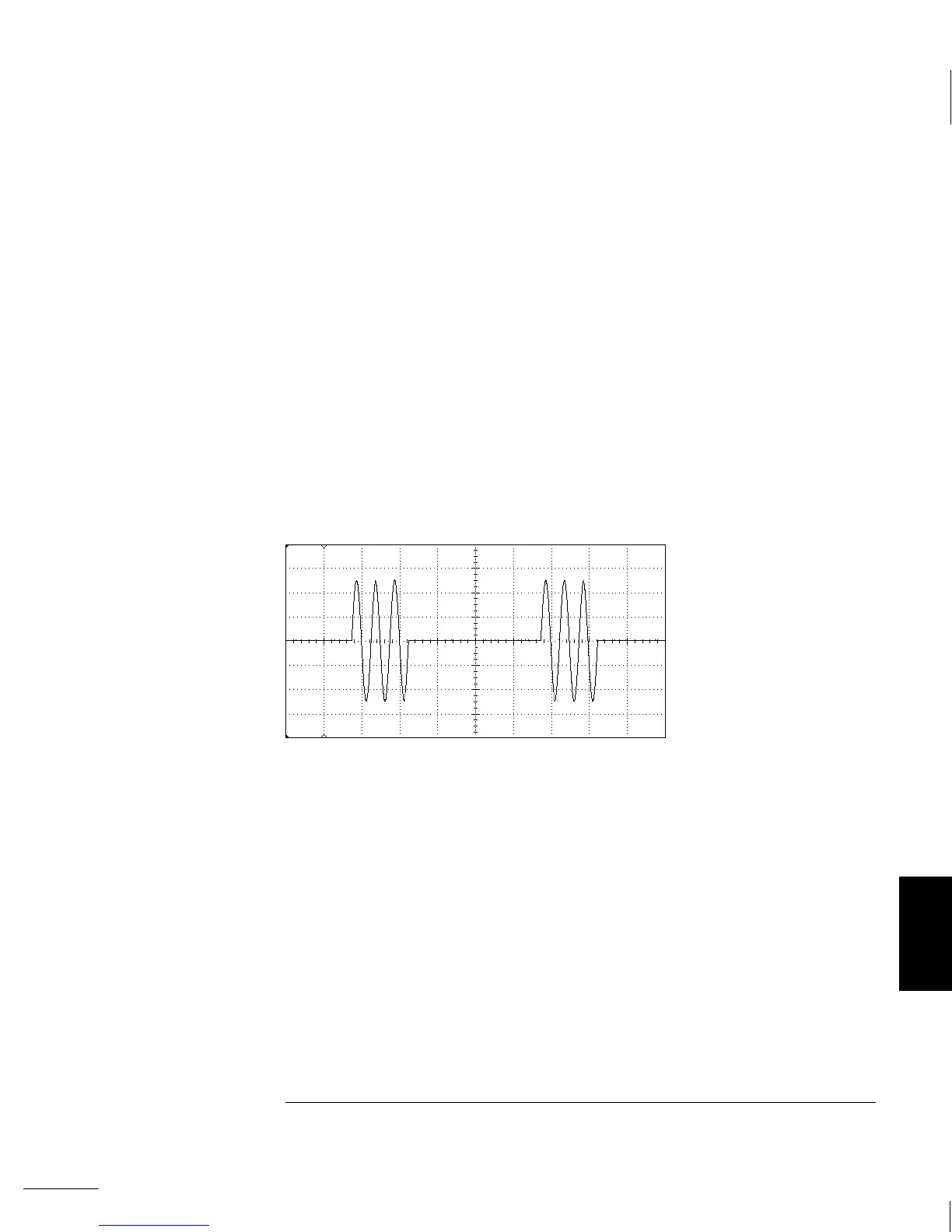
A three-cycle bursted sine wave with 100 Hz burst rate.
7
Chapter 7 Tutorial
Modulation
291