Overall
Block
Diagram
Figure
4-2
shows
the
overall
block
diagram
of
the
4349B
.
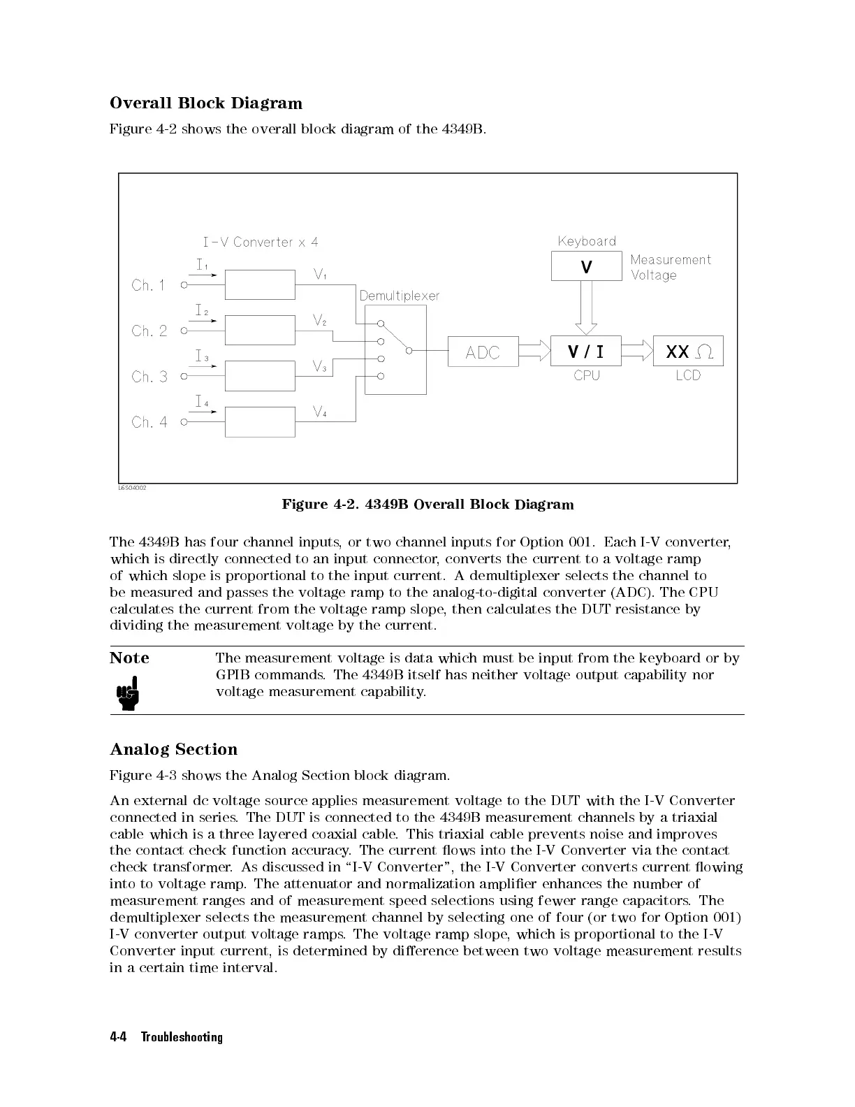
Figure
4-2.
4349B
Overall
Block
Diagram
The
4349B
has
four
channel
inputs,
or
two
channel
inputs
for
Option
001.
Each
I-V
converter
,
which
is
directly
connected
to
an input
connector
,
converts
the
current
to
a
voltage
ramp
of
which
slope
is
proportional
to
the input
current.
A
demultiplexer
selects
the
channel
to
be
measured
and
passes
the
voltage
ramp to
the
analog-to-digital
converter
(ADC).
The
CPU
calculates
the
current
from
the
voltage
ramp slope
, then
calculates
the
DUT
resistance
by
dividing the
measurement
voltage
by
the
current.
Note
The
measurement voltage
is data
which
must
be
input
from
the
keyboard
or
by
GPIB
commands.
The 4349B
itself
has
neither
voltage
output
capability
nor
voltage
measurement capability
.
Analog
Section
Figure 4-3 shows the Analog Section block diagram.
An external dc voltage source applies measurement voltage to the DUT with the I-V Converter
connected in series
. The DUT is connected to the 4349B measurement channels by a triaxial
cable which is a three layered coaxial cable
. This triaxial cable prevents noise and improves
the
contact check function accuracy
. The current ows into the I-V Converter via the contact
check transformer
. As discussed in \I-V Converter", the I-V Converter converts current owing
into to voltage
ramp. The attenuator and normalization amplier enhances the number of
measurement ranges and of measurement speed selections using fewer range capacitors. The
demultiplexer selects the measurement channel by selecting one of four (or two for Option 001)
I-V converter output voltage ramps. The voltage ramp slope, which is proportional to the I-V
Converter input current, is determined by dierence between two voltage measurement results
in a certain time interval.
4-4 Troubleshooting
 Loading...


