Digital
Section
Figure
4-5
shows
the
Digital
Section
block
diagram.
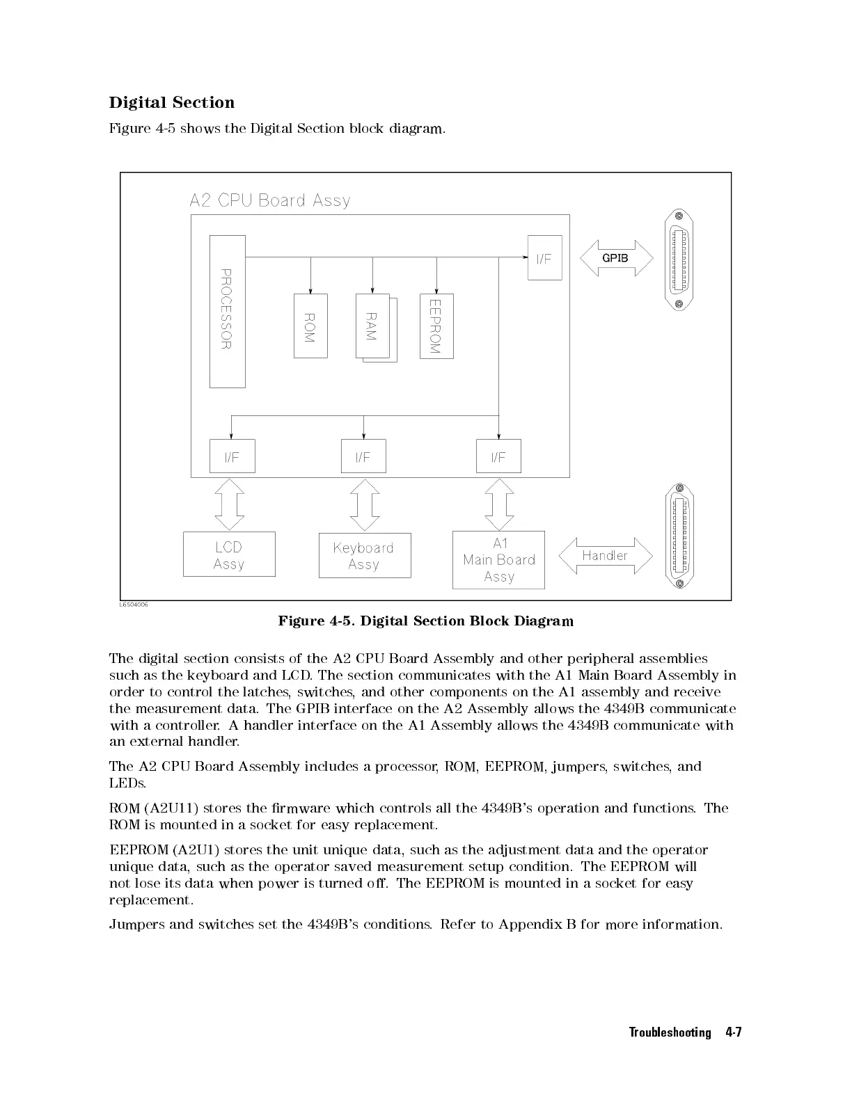
Figure
4-5.
Digital
Section
Block
Diagram
The
digital
section
consists
of the
A2 CPU
Board Assembly
and
other
peripheral
assemblies
such
as
the
keyboard
and LCD
.The
section communicates
with
the
A1
Main
Board
Assembly
in
order
to
control
the
latches,
switches,
and other
components on
the
A1
assembly
and
receive
the
measurement
data.
The
GPIB interface
on the
A2 Assembly
allows the
4349B
communicate
with
a
controller.
A handler
interface on
the A1
Assembly allows
the 4349B
communicate
with
an
external
handler
.
The A2 CPU Board Assembly includes a processor
, ROM, EEPROM, jumpers
, switches
, and
LEDs.
ROM (A2U11) stores the rmware which controls all the 4349B
's operation and functions
. The
ROM is mounted in a socket for easy replacement.
EEPROM (A2U1) stores the unit unique data, such as the adjustment data and the operator
unique data, such as the operator saved measurement setup condition. The EEPROM will
not lose its data when power is turned o. The EEPROM is mounted in a socket for easy
replacement.
Jumpers and switches set the 4349B's conditions. Refer to Appendix B for more information.
Troubleshooting 4-7
 Loading...


