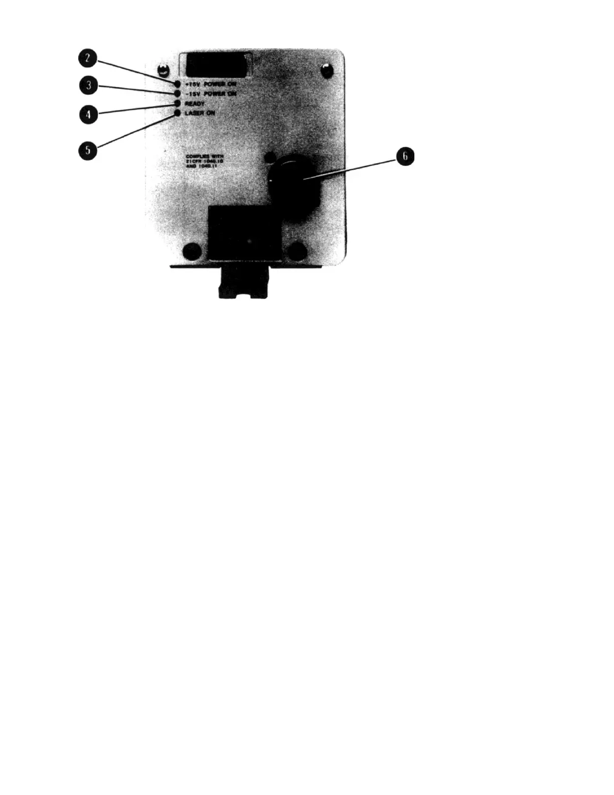
2. +15V POWER ON GREEN LED
3. -15V POWER ON GREEN LED
4. READY GREEN LED
LASER ON AMBER LED
18-PIN CONNECTOR (TWIST-LOCK) (A1J2)
LED lights when +15 Vdc power is applied to
the HP 5517B. This LED extinguishes if the
+15V fuse opens.
LED lights when -15 Vdc power is applied to the HP 5517B.
This LED extinguishes if the -15V fuse opens..
LED remains off while heating rod to normal operating
temperature. At this point the READY LED begins to flash
and continues to do so until the laser head reaches operating
temperature. When the laser head is ready for use, the
READY LED stays on steady (i.e., Laser has achieved lock and
is now generating a stable reference signal).
LED lights to indicate that the high voltage power supply
(HVPS) is on and that laser light is being emitted.
Provides connection point for external power supply input and
allows the reference signals (REF and ~REF) to connect to
other system components (via HP 10791A/B/C or HP
10793A/B/C cables).
Figure 3-2. HP 5517B Rear Panel Connectors and Indicators
3-10. OPERATING MODES

 Loading...


