CONNECTORS
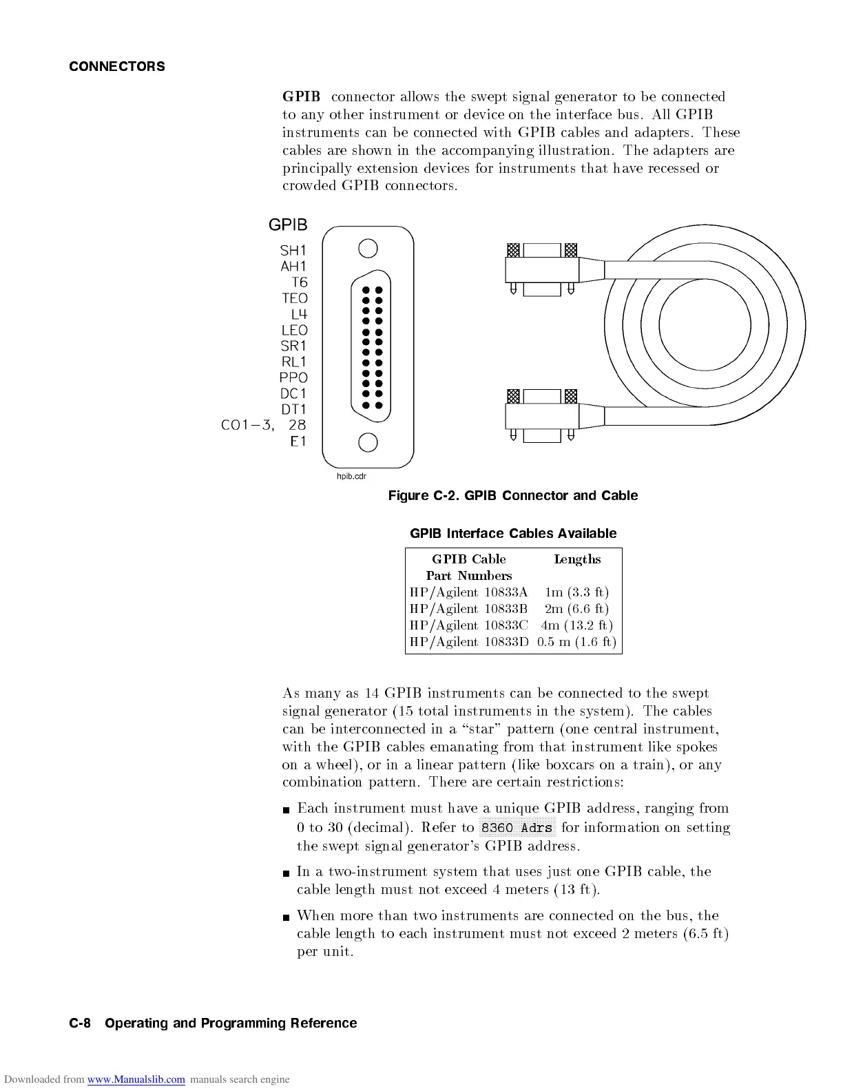
GPIB
connector allows the swept signal generator to be connected
to any other instrument or device on the interface bus. All GPIB
instruments can b e connected with GPIB cables and adapters. These
cables are shown in the accompanying illustration. The adapters are
principally extension devices for instruments that have recessed or
crowded GPIB connectors.
Figure C-2. GPIB Connector and Cable
GPIB Interface Cables Available
GPIB Cable
Part Numbers
Lengths
HP/Agilent 10833A 1m (3.3 ft)
HP/Agilent 10833B 2m (6.6 ft)
HP/Agilent 10833C 4m (13.2 ft)
HP/Agilent 10833D 0.5 m (1.6 ft)
As many as 14 GPIB instruments can be connected to the swept
signal generator (15 total instruments in the system). The cables
can be interconnected in a \star" pattern (one central instrument,
with the GPIB cables emanating from that instrument like spokes
on a wheel), or in a linear pattern (lik
eboxcars on a train), or any
combination pattern. There are certain restrictions:
Each instrumentmust have a unique GPIB address, ranging from
0 to 30 (decimal). Refer to
NNNNNNNNNNNNNNNNNNNNNNNNNNNNN
8360 Adrs
for information on setting
the swept signal generator's GPIB address.
In a two-instrument system that uses just one GPIB cable, the
cable length must not exceed 4 meters (13 ft).
When more than two instruments are connected on the bus, the
cable length to each instrumentmust not exceed 2 meters (6.5 ft)
per unit.
C-8 Operating and Programming Reference
 Loading...


