1b-49
Operation Reference
Function
CAUTION Applying a signal source to the RF output port that exceeds the power level
listed or maintaining a signal source at the RF output for an extended period
of time may damage the instrument.
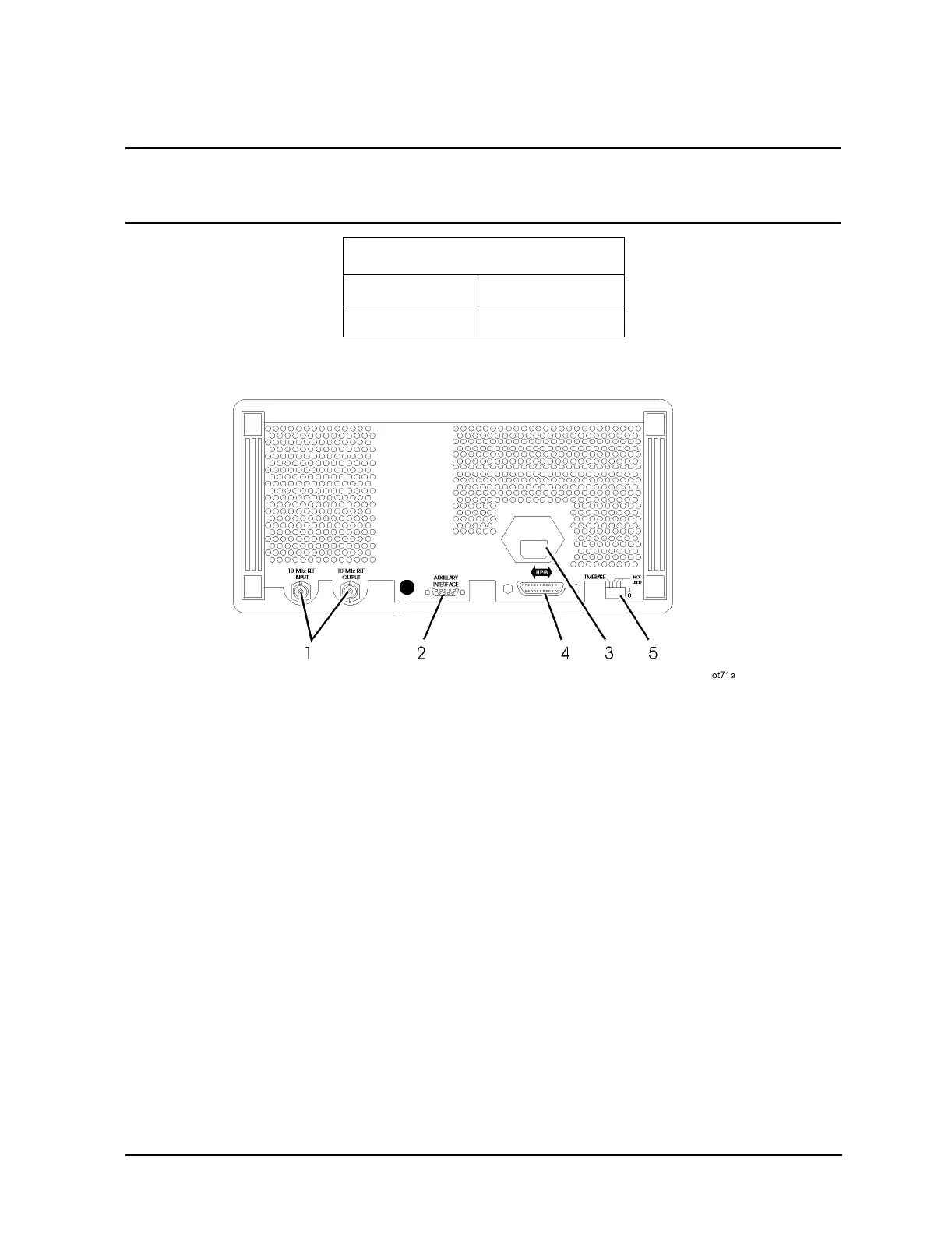
Rear Panel
1. 10 MHz REF INPUT and OUTPUT
These connectors provide the input and output ports for the instrument’s timebase
reference. The instrument will lock to a 2 MHz, 5 MHz, or 10 MHz external reference
source connected to the input that is within ±5 ppm. When the internal timebase is being
used, the output connector provides a 10 MHz, 1 Vrms level signal.
2. DISPLAY CONTRAST
This knob controls the front panel display contrast. Display contrast can be optimized for
viewing the display from above, below, or directly in front of it.
3. AUXILIARY INTERFACE
Connect the 83300A Remote Interface or the 83301A Memory Interface to this connector
for operation with the instrument. Refer to "Remote Interface" and "Memory Interface" in
Reverse Power Protection
≤ 2000 MHz 50 watts into 50Ω
> 2000 MHz 25 watts into 50Ω

 Loading...


