7-2
Adjustments
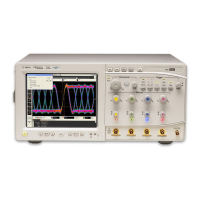
Test Equipment
Test Equipment
The required test equipment for the adjustments is listed in Table 5-1. Along with the
required test equipment, this table lists the critical specifications of each, the
recommended model number, and the adjustments that this equipment is used to perform.
Equipment Setup for Automated Tests
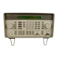
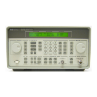
The complete test equipment setup includes the 8648 that is being tested (the DUT), a
personal computer (PC) that runs the adjustment software, and the various instruments
that make up the electronic test equipment. The PC must have a GPIB Interface Bus
installed in one of its card slots. The DUT is connected to the PC’s GPIB card via a GPIB
cable. Another GPIB cable connects the PC to the electronic test equipment. The electronic
test equipment must be connected together via additional GPIB cables.
NOTE Although the test setup illustrations do not show the PC or the GPIB cable
connections, these connections are required to perform the automated tests
and adjustments.
Test Point Extender
One additional adapter is required to perform the adjustments. Several adjustments use
J31 as a test point on the motherboard of the DUT. The adapter is used to extend the J31
test point so that it can be accessed for the adjustments. The J31 Test Point Extender (part
number 08648-60175) and service support software can be obtained, together, by ordering
part number 08648-60180.
You can also build the J31 Test Point Extender by using the following instructions. J31 is a
six-pin connector on the motherboard. The text point extender consists of a six-pin
connector housing attached to six crimped wires that will plug into J31. The six wires
should be of different colors so that you can differentiate between the wires with just a
glance. A good method of differentiating between the wires is by using the resistor color
code values to identify the pin number. For example, the value of orange in the resistor
color code is “3”; so the orange wire is connected as pin 3 of the test point extender.

 Loading...


