Power Meter Operation
Recorder Outputs
Agilent E4419B User’s Guide 2-65
Recorder Outputs
The rear panel Recorder Output connectors (A and B) produce a dc voltage
that corresponds to the power level in Watts of the channel, depending on
the measurement mode. This dc voltage ranges from 0 to +1 Vdc. The
output impedance is typically 1 kΩ . Channel and display offsets, and duty
cycle have no effect on the Recorder Outputs.
For example, the Recorder Outputs can be used to;
• record swept measurements on an X-Y recorder
• level an output from a source using external leveling, or
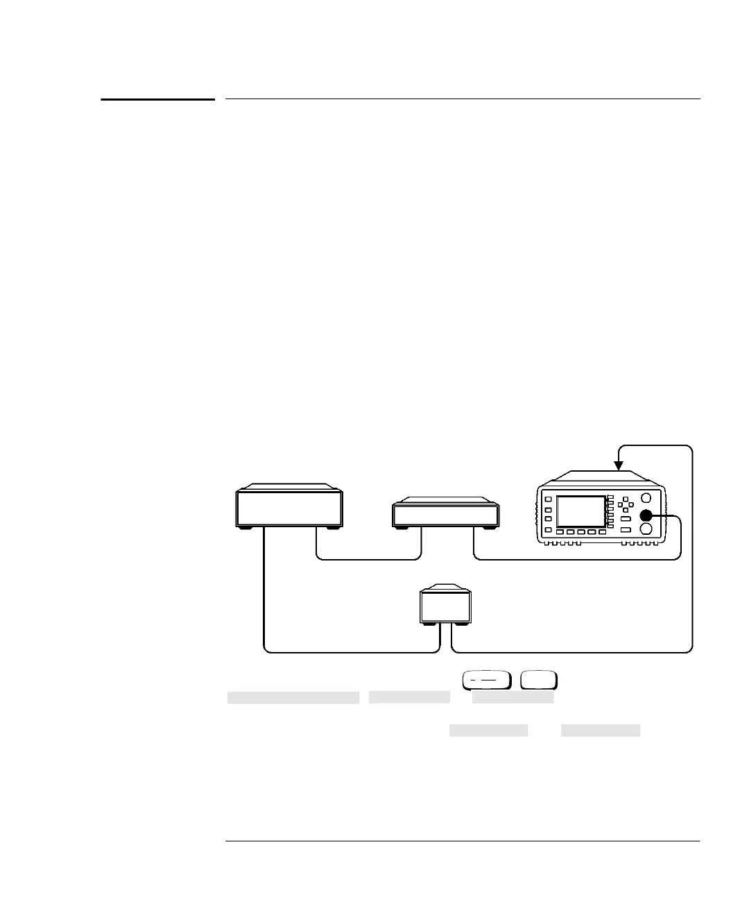
• monitor the output power on a strip chart recorder. A setup for
recording swept measurements is shown in Figure 2-21.
See Figure 2-23 for details on which power meter functions are
implemented in the recorder output.
Figure 2-21: Test Setup for Recording Swept Measurements
To access the “Recorder” menu press , ,
, or depending on which
channel you want to set up. This menu allows you to switch the Recorder
Output signal either on or off. The and softkeys
allow you to enter the input power level that you want to represent the
1V
dc
maximum and 0 V
dc
minimum output voltage of the Recorder
Output.
Device
Power Meter
CHANNEL A
INPUT
OUT
X-Y Recorder
Swept Source
Under Test
IN
RF OUT
SWEEP
OUT
X-AXIS (FREQUENCY) Y-AXIS (POWER)
RECORDER
OUTPUT
A
System
Inputs
More
Recorder Output
Channel A Channel B
Max Power Min Power
HP4402.book Page 65 Thursday, November 30, 2000 1:39 PM