Getting Started
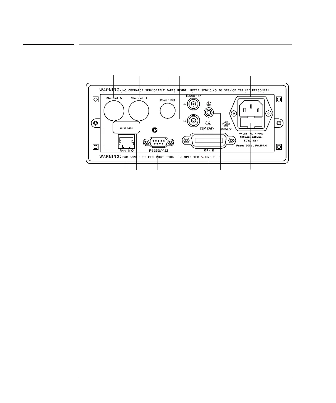
The Rear Panel at a Glance
1-16 Agilent E4419B User’s Guide
The Rear Panel at a Glance
1. Channel A (Option 002 or 003 only)
2. Channel B (Option 002 or 003 only)
3. Power Ref (Option 003 only)
The power reference output is a 50 Ω type N connector. The output
signal is used for calibrating the sensor meter combination.
4. Recorder Outputs
These outputs produces a dc voltage that corresponds to the power
level of the channel input. Refer to “Recorder Outputs”, on
page 2-65 for further information.
5. Power socket
This power meter has an auto configuring power supply. This
allows it to operate over a range of voltages without manually
being set to a certain voltage.
6. Fuse
An F3.15AH fuse is installed for all voltage supplies.
7. GP-IB
This connector allows the power meter to be controlled remotely
using the General Purpose Interface Bus.
8. RS232/422
134
5
6
7
8
10 9
2
11
N279
HP4402.book Page 16 Thursday, November 30, 2000 1:39 PM