1-23
Troubleshooting
Troubleshooting Assembly–Level Problems
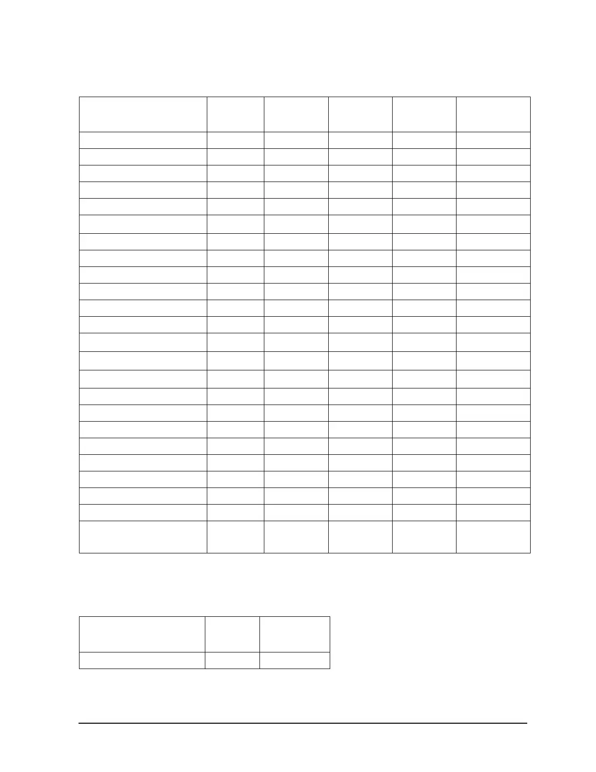
Table 1-11 E8267C, Option 520, Power Supply vs. Assembly Matrix (4 of 5)
Motherboard Test Points:
LED
–5.2V
LED
–5.2 V2
a
a. Voltage regulator on motherboard
+ 12 VDC
LED
+ 15 VSTBY Fan Voltage
Power Supply P235-E4,5
Sampler P22-4,19
Frac N P32-4,19
Reference P42-4,19
Lowband Output P52-4,19
YTO Driver P112-1,2,26,27
b
b. Originates on YTO Driver
ALC/Scan P122-1,26
Mod Gen P132-1,26
CPU P223-1 P223-21
I/Q Multiplexer P152-1 P152-26
Baseband Generator P162-1 P162-26
Microwave Interface P201-31,32
20 GHz Doubler J32-8 J32-1,3
c
c. Originates on Microwave Interface
20 GHz Mod Filter J31-8 J31-1,3
c
20 GHz I/Q Modulator J34-9
c
40 GHz Doubler J36-8, J33-8
Attenuator
Lowband Coupler/Det
Front Panel/Display P11-43
Keyboard
Display Backlight
1E5 OCXO
Rear Panel P241-9,10 P241-5,6,7,8
Fan Fan+ P252-2, P251-2
Fan- P252-1, P251-1
Table 1-12 E8267C, Option 520, Power Supply vs. Assembly Matrix (5 of 5)
Motherboard Test Points:
LED
+1.95VD1
a
a. Voltage regulator on motherboard
LED
+1.8VD_1
a
Baseband Generator P161-52,118 P161-55,56,120-122