Home
Agilent Technologies
Laboratory Equipment
G7129A
Agilent Technologies G7129A User Manual
4
of 1
of 1 rating
369 pages
Give review
Manual
Specs
To Next Page
To Next Page
To Previous Page
To Previous Page
Loading...
Agilent InfinityLab LC
Series Vialsampl
ers User Manual
223
8M
a
i
n
t
e
n
a
n
c
e
Introduction to Maintenance
Introduction to Maintenance
The module is designed for easy ma
intenance. Maintenance can be done from
the front with module in place in the system stack.
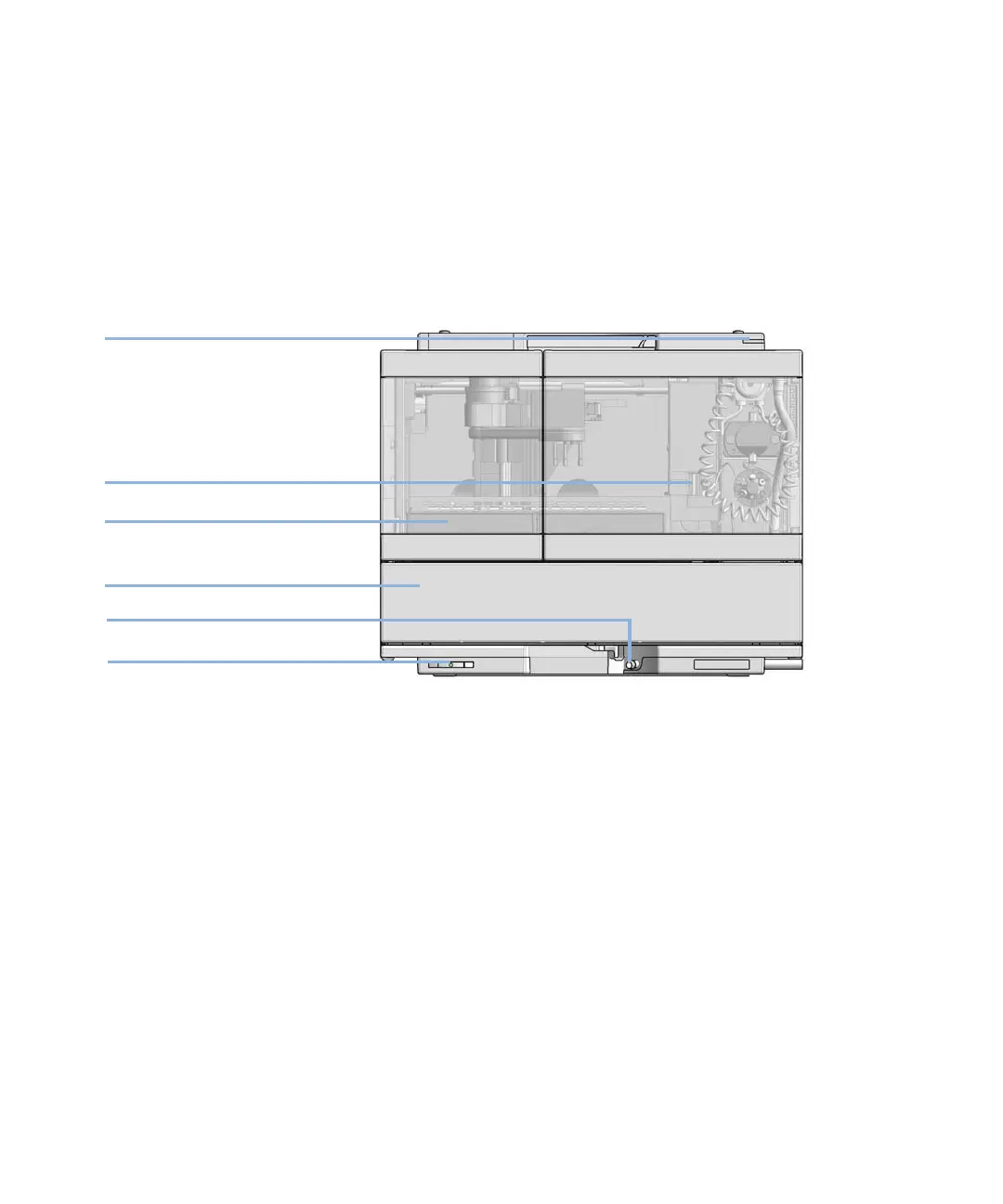
Figure
33
Overview of th
e Vialsampler
Status indicator
Needle assembly
Drawer
Column shelf
Leak drain
Power switch
222
224
Table of Contents
In This Book:
3
1 Introduction
9
Product Description (G7129A)
10
Features (G7129A)
11
Product Description (G7129B)
12
Features (G7129B)
13
Product Description (G7129C)
14
Features (G7129C)
15
Overview of the Module
16
Operating Principle
18
Sampling Sequence
18
Needle Parkstation
23
Hydraulic Box
24
Transport Assembly
26
Leak and Waste Handling
27
Leak Sensor
31
Waste Guidance
31
Waste Concept
32
2 Site Requirements and Specifications
33
Site Requirements
34
Site Requirements
34
Power Considerations
34
Power Cords
35
Room Size and Ventilation
36
Bench Space
36
Condensation
37
Physical Specifications
38
Performance Specifications
39
Performance Specifications (G7129A)
39
Performance Specifications (G7129B)
42
Performance Specifications (G7129C)
45
Specifications of the Sample Cooler
47
Specifications of the Sample Thermostat
49
Specifications of the Integrated Column Compartment
51
Physical Specifications Agilent InfinityLab LC Series Integrated Column Compartment (G7130A)
51
Performance Specifications Agilent InfinityLab LC Series Integrated Column Compartment (G7130A)
52
3 Using the Module
53
Magnets
55
Turn on/off
56
Status Indicators
58
Vial Drawers and Trays
59
List of Drawers and Trays
59
Exchange Drawers
62
Insert a Vial Into the Sampler
65
Install the External Tray
67
Choice of Vials and Caps
70
Compatible Vials and Caps for the 2 mL Vial Drawers
70
Compatible Vials and Caps for the 6 mL Vial Drawer
73
Install the Optional Integrated Column Compartment
74
Unpacking the Unit
74
Install the Integrated Column Compartment
76
Install a Column in the ICC
82
Remove a Column from the ICC
86
Install the Column Shelf
88
Install the Column ID Upgrade Kit
92
Connect a Column Identification Tag to the Tag Reader
94
Using the Optional Integrated Column Compartment
96
Dashboard
96
Control Interface
97
Control
98
Method Parameters
99
Online Signals
101
Column Assignment
102
Column Tag Information Table
103
Using Column Identification Tags
104
Install the Optional Sample Cooler/Sample Thermostat
116
Unpacking the Unit
116
Install the Sample Cooler/Sample Thermostat
117
Using the Optional Sample Cooler/Sample Thermostat
123
Dashboard
123
Control Interface
124
Control
125
Temperature Mode
127
Online Signals
128
Reporting Sample Temperature
129
Operation Information
130
Transporting the Sampler
132
Prepare a Sampler Without Cooler/Thermostat for Transportation
132
Prepare a Sampler with Cooler/Thermostat for Transportation
133
Install the Transport Protection Foam
135
Agilent Local Control Modules
137
4 Preparing the Module
139
Leak and Waste Handling
140
Preparing the Module
141
Solvent Information
142
Recommended Wash Solvents
142
Solvent Compatibility of Tubings for Peristaltic Pumps
143
General Information about Solvent/Material Compatibility
144
Capillary Color Coding Guide
149
Installing Capillaries
150
Flow Connections to the Vialsampler
152
Setting up the Vialsampler
154
Control Settings
158
Method Parameter Settings
160
Injector Programm
164
Module Configuration View
165
5 Optimizing Performance
166
Optimization for Lowest Carryover
167
Using the Automated Needle Wash (Wash Port)
167
Using an Injector Program
169
General Recommendation for Lowest Carryover
170
Fast Injection Cycle and Low Delay Volume
171
Overlapped Injection Mode
171
General Recommendations for Fast Injection Cycle Times
172
Precise Injection Volume
173
Draw and Eject Speed
174
Choice of Rotor Seal
175
6 Troubleshooting and Diagnostics
176
Status Indicators
177
Overview of Tests and Tools
178
Maintenance and Troubleshooting Tools
179
Maintenance Positions
179
Gripper Verification
183
Injector Steps
184
Park Arm
186
Diagnostic Tests
187
Sample Cooler Function Test
187
Heater Test
188
Agilent Lab Advisor Software
189
7 Error Information
190
What are Error Messages
192
General Error Messages
193
Timeout
193
Shutdown
194
Remote Timeout
195
Lost CAN Partner
195
Leak Sensor
196
Leak Sensor Open
197
Leak Sensor Short
198
Compensation Sensor Open
199
Compensation Sensor Short
199
Fan Failed
200
Vialsampler Error Messages
201
Command failed errors
201
Metering home failed
202
Automatic Referencing procedure failed
202
Needle up/down failed errors
203
Missing vial errors
204
Motor overtemp
205
Motor alignment failed
206
Invalid vial position errors
207
Cleanup after abort failed
208
Wash procedure failed
208
Start of maintenance procedure failed errors
209
Injection valve position not found
209
Cannot move metering, the metering type definition is incorrect
210
Initialization failed errors
210
Unexpected block during axis movement
211
Timeout during axis movement
212
Sample Cooler/Sample Thermostat Error Messages
213
Sample temperature control voltage too low, check fuses and wires
213
Sample temperature control switched off due to condensate
213
Sample temperature control switched off due to overpressure
214
Sample temperature control sensor electronics calibration failed
214
Sample temperature control switched off due to supply voltage drop
215
Cooler condensate sensor defect
215
Cooler PCB is in error mode
215
Cooler condenser fan failed
216
Thermostat communication error
216
Heater defect
216
Heater in operating error
217
Thermostat sensor defect
217
Compressor has error
217
Sample Thermostat unknown
218
Thermostat fan defect
218
Integrated Column Compartment (ICC) Heater Error Messages
219
Wait for temperature function timed out
219
Heater over-current protection active
219
A heater sensor reading failed
220
Trend analysis for the heater temperature sensors failed
220
Maximum heater temperature exceeded
221
Column heater not connected
221
8 Maintenance
222
Introduction to Maintenance
223
Warnings and Cautions
224
Overview of Maintenance
226
Cleaning the Module
227
Remove and Install Doors
228
Exchange the Needle Assembly
229
Exchange the Needle Seat Assembly
235
Exchange the Sample Loop Assembly
241
Exchange the Rotor Seal
245
Exchange the Metering Seal and Piston
250
Replace the Analytical Heads
255
Exchange the Gripper Arm
258
Replace the Peristaltic Pump Cartridge
261
Exchange the Wash Port Assembly
263
Replace the Module Firmware
269
Replace the Sample Cooler/Sample Thermostat
270
9 Parts and Materials for Maintenance
275
Standard Parts For Maintenance
276
PM Kits
276
Needle Assemblies
276
Needle Seats
276
Sample Loops
277
Rotor Seals for Injection Valves
277
Metering Seals for Analytical Heads
277
Capillary Connections
278
Other Parts
278
Accessory Kits
279
Accessory Kit for 1290 Infinity II Vialsampler
279
Accessory Kit for 1260 Infinity II Vialsampler
281
Vial Drawers and Trays
283
Cartesian Vial Drawers
283
Classic Vial Drawers
284
External Tray
285
Multidraw Kits
286
Multidraw Kit
286
Large Volume Injection Kit
286
Sample Thermostat Upgrade
287
Integrated Column Compartment
288
Column ID Upgrade Kit
289
Parts for 900 µL Injection Upgrade
290
Cabinet and Door Kits
291
Cabinet Kit
291
Door Kit
293
Door Insulation Kit
294
Analytical Head Assembly (100 µL)
295
Analytical-Head Assembly (900 µL)
296
Analytical Head Assembly (40 μL)
297
2 Position/6 Port Injection Valve, 600 bar
298
2 Position/6 Port Injection Valve, 800 bar
299
2 Position/6 Port Injection Valve, 1300 bar
300
10 Identifying Cables
301
Cable Overview
302
Analog Cables
304
Remote Cables
306
CAN/LAN Cables
310
RS-232 Cables
311
USB
312
11 Hardware Information
313
Firmware Description
314
Electrical Connections
317
Rear View of the Module
318
Serial Number Information
318
Interfaces
319
Overview Interfaces
321
ERI (Enhanced Remote Interface)
323
USB (Universal Serial Bus)
325
Setting the 6-bit Configuration Switch
326
Special Settings
328
Instrument Layout
330
Early Maintenance Feedback (EMF)
331
12 LAN Configuration
332
What You Have to Do First
333
TCP/IP parameter configuration
334
Configuration Switches
335
Initialization Mode Selection
336
Dynamic Host Configuration Protocol (DHCP)
338
General Information (DHCP)
338
Setup (DHCP)
339
Manual Configuration
341
With Telnet
342
PC and Agilent ChemStation Setup
345
PC Setup for Local Configuration
345
Agilent ChemStation Setup
348
13 Appendix
354
General Safety Information
355
General Safety Information
355
Safety Standards
355
General
355
Before Applying Power
356
Ground the Instrument
356
Do Not Operate in an Explosive Atmosphere
357
Do Not Remove the Instrument Cover
357
Do Not Modify the Instrument
357
In Case of Damage
357
Solvents
358
Symbols
359
Waste Electrical and Electronic Equipment (WEEE) Directive
361
Refrigerant
362
Radio Interference
365
Sound Emission
366
Solvent Information
367
Agilent Technologies on Internet
368
In This Book
369
Other manuals for Agilent Technologies G7129A
Quick Guide
82 pages
4
Based on 1 rating
Ask a question
Give review
Questions and Answers:
Need help?
Do you have a question about the Agilent Technologies G7129A and is the answer not in the manual?
Ask a question
Agilent Technologies G7129A Specifications
General
Brand
Agilent Technologies
Model
G7129A
Category
Laboratory Equipment
Language
English
Related product manuals
Agilent Technologies G7129B
369 pages
Agilent Technologies G7129C
369 pages
Agilent Technologies G7117C
230 pages
Agilent Technologies G7116A
203 pages
Agilent Technologies G7104C
310 pages
Agilent Technologies G7166A
272 pages
Agilent Technologies WR G7115A
82 pages
Agilent Technologies G1888
192 pages
Agilent Technologies G1883
157 pages
Agilent Technologies G1367A
286 pages
Agilent Technologies G1313A
292 pages
gc/ms series
148 pages
 Loading...