Agilent N5161A/62A/81A/82A/83A MXG Signal Generators Service Guide
Troubleshooting
Troubleshooting Assembly Level Problems
1-34
On the N5181A/82A/83A:
a. Put the instrument into diagnostics mode:
Power up the instrument while holding the Preset hardkey.
The diagnostic service menu is displayed.
b. Press
Continue > Next Page > Next Page > Bootup in no hardware mode [ ] (Verify an “x” is displayed in the “[ ]” (example: [x]))
The instrument is now in the “Bootup in no hardware mode”.
c. Verify the instrument is connected to the LAN.
d. Re-load the most recent version of firmware.
If the instrument boots up without errors, proceed to step 7.
If the firmware still cannot be loaded, proceed to step 6.
6. If reloading the firmware does not correct the symptom, replace the A3 RF assembly.
7. After replacing the A3 RF assembly in a model N5183A instrument, go to Chapter 4, "Post-Repair Procedures and Performance
Verification".
A6 DC-AC Inverter Interface Board (N5181A/82A/83A)
The A6 DC-AC Inverter Interface Board controls the Cold Cathode Fluorescent Tube (CCFT) backlight on the LCD Display module and
converts a dc voltage to an ac voltage. Varying the dc voltage on the inverter will alter the backlight brightness. To determine if the A6
DC-AC Inverter Interface Board is the faulty assembly, complete the following procedure.
1. Turn the signal generator off.
2. Remove the front panel. Refer to Chapter 3, "Assembly Replacement".
3. Position the signal generator with the A3 RF assembly facing up.
4. Re-connect the W1 ribbon cable to the A3 RF assembly.
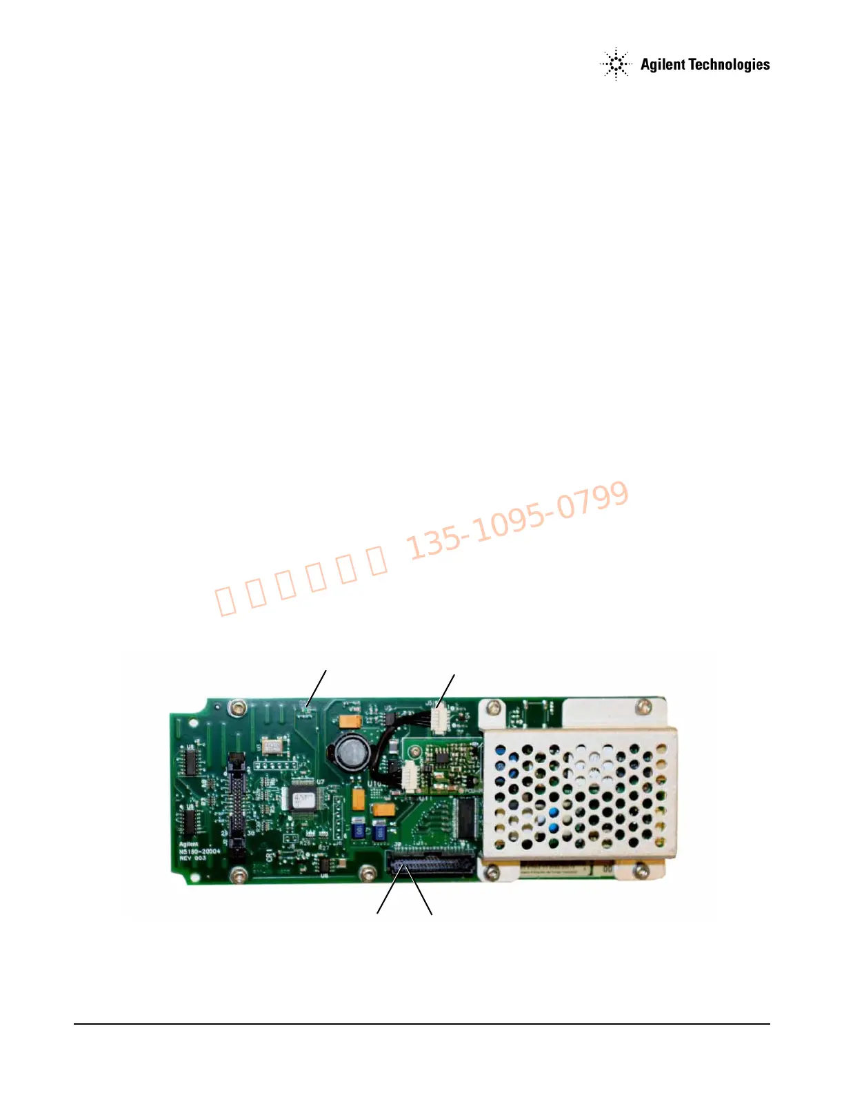
5. Use Figure 1-24 on page 57 to locate line switch S1. Press line switch S1 to turn the signal generator on.
6. Verify that the PIC processor is on:
• LED DS1, refer to Figure 1-10, should blink at a rate of 2 Hz. When DS1 is blinking the PIC processor has initialized and is
operational.
Figure 1-10 LED DS1 and A6J5-1
 Loading...


