Installation Note E4440-90613 19
Installation Procedure
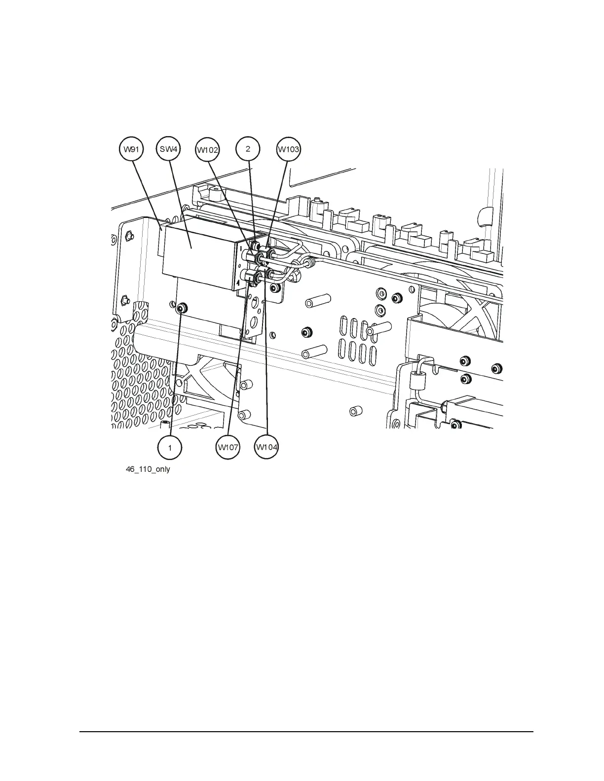
16.Refer to Figure 12. Locate and remove cable W107 (Switch SW4 Port 4 to W34 on the
RYTHM/SBTX). Discard this cable, since it will be replaced by another cable.
Figure 12 Option 110 Cable Location
17.Locate and remove cable W102 (Switch SW4 Port 3 to Preamplifier). This cable will
be replaced later. It is removed to allow the Switch Assembly to be removed.
18.Locate and remove cable W103 (A15 Attenuator to Switch SW4 Port 1). This cable
will be replaced later. It is removed to allow the Switch Assembly to be removed.
19.Locate and remove cable W104 (Preamplifier Output to Switch SW4 Port 3). This
cable will be replaced later. It is removed to allow the Switch Assembly to be removed.
20.Locate and remove ribbon cable W91 (Option Driver Assembly to Switch SW4). This
cable will be replaced later. It is removed to allow the Switch Assembly to be removed.
21.Remove the three screws (2) that attach the Switch Bracket to the Mixer Bracket. Lift
the Switch Bracket Assembly from the instrument.
22.Locate Switch SW5 (87222-60015) from the kit. Install Switch SW5 to the Bracket
below Switch SW4 with three screws (0515-1934) Torque to 6 in-lbs with a Torx T-8
driver.
23.Re-Install Switch Assembly to Mixer Bracket with three screws (0515-0372) Leave
screws loose to allow cables to be installed.

 Loading...


