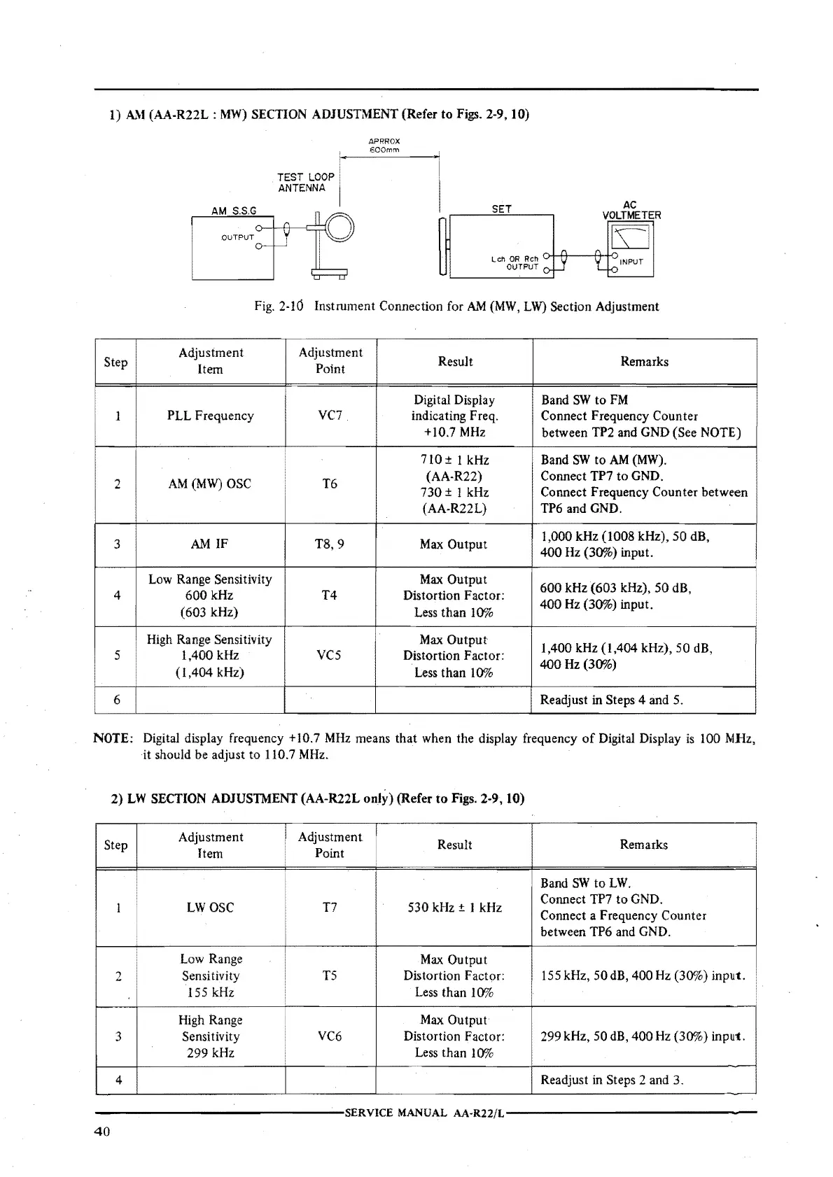
I)
AM
(AA-R22L:
MW)
SECTION
ADJUSTMENT
(Refer
to
Figs.
2-9, 10)
SET
Leh
OR Reh
OUTPUT
AC
VOLTMETER
Fig. 2-10 Instrument Connection for AM (MW,
LW)
Section Adjustment
Step
Adjustment Adjustment
Result Remarks
Item
Point
Digital Display Band
SW
to
FM
1
PLL
Frequency
VC7
indicating Freq. Connect Frequency Counter
+10.7 MHz between TP2 and GND (See NOTE)
710
± l kHz Band
SW
to
AM
(MW).
2
AM(MW) OSC T6
(AA-R22)
Connect TP7
to
GND.
730
± I kHz
Connect Frequency
Counter
between
(AA-R22L)
TP6 and GND.
3
AM
IF
T8, 9
Max
Output
1,000
kHz
(1008
kHz},
50
dB,
400
Hz (30%) input.
Low Range Sensitivity
Max
Output
600
kHz
(603
kHz),
50
dB,
4
600
kHz
T4
Distortion
Factor:
(603 kHz)
Less
than
I
0%
400
Hz (30%) input.
High Range Sensitivity
Max
Output
1,400 kHz
(l,404
kHz),
50
dB,
s
1,400
kHz
vcs
Distortion
Factor:
(1,404
kHz)
Less
than
l 0%
400
Hz (30%)
6
Readjust in Steps 4 and
5.
NOTE:
Digital display frequency +10.7
MHz
means tha.t when
the
display frequency
of
Digital Display is 100 MHz,
it should be adjust to I 10.7 MHz.
2)
LW
SECTION
ADJUSTMENT
(AA-R22L
only)
(Refer
to
Figs.
2-9, 10)
Adjustment I
Adjustment
I
Step
Item
Point
Result
Remarks
Band
SW
to
LW.
l
LWOSC
T7
530 kHz ± I kHz
Connect TP7
to
GND.
Connect a Frequency
Counter
between TP6 and GND.
Low Range
Max
Output
2
Sensitivity
TS
Distortion Factor:
155 kHz,
50
dB, 400 Hz (30%)
input.
155 kHz Less
than
I
0%
High Range Max
Output
3
Sensitivity
VC6 Distortion Factor: 299 kHz, 50 dB,
400
Hz
(3()l}h)
input.
299
kHz
Less
than
l()';io
4
Readjust in Steps 2 and
3.
---------------SERVICE
MANUAL
AA·Rll/L---------------
40
 Loading...