i
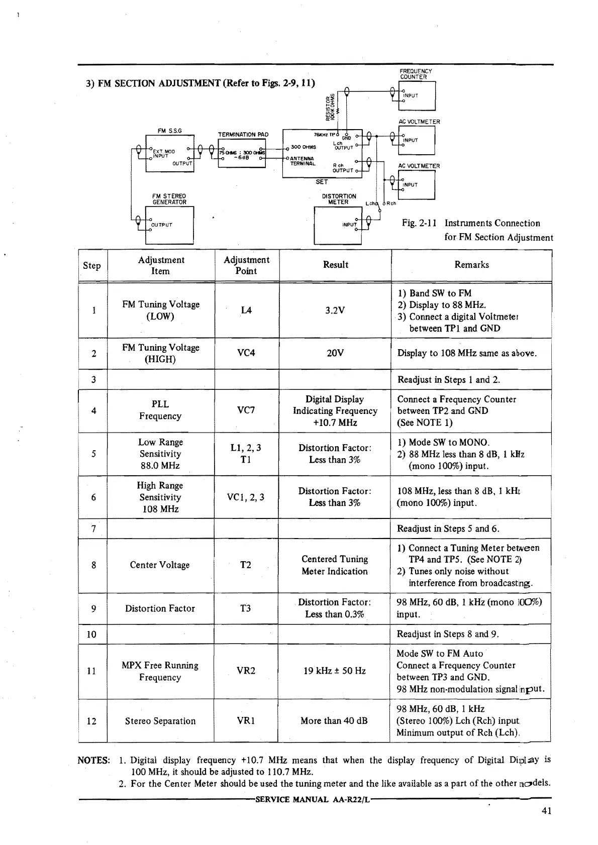
3)
FM
SECTION
ADJUSTMENT
(Refer
to
Figs.
2-9, 11)
Step
I
2
3
4
5
6
7
8
9
10
11
12
FM
S.S.G
TERMINATION
PAO
761(Hr
Tf>
EXT.
MOD
INPUT
o-+1+-++t01SO!t.<S :
000
OtWSQ-i---iK>
300
OHMS
FM
STEREO
GENERATOR
OUTPUT
Adjustment
Item
FM
Tuning Voltage
(LOW)
FM
Tuning Voltage
(HIGH)
PLL
Frequency
Low Range
Sensitivity
88.0MHz
High Range
Sensitivity
108
MHz
Center Voltage
Distortion Factor
MPX
Free Running
Frequency
Stereo Separation
-6d6
o+---iK>ANTENNA
TERMINAL
R
ch
OVTPUT
SET
Adjustment
Result
Point
L4 3.2V
VC4
20V
Digital Display
VC7
Indicating Frequency
+10.7 MHz
LI,
2, 3
Distortion Factor:
Tl
Less than
3%
Distortion Factor:
VCI, 2, 3
Less than
3%
T2
Centered Tuning
Meter Indication
T3
Distortion Factor:
Less than
0.3%
VR2 19 kHz±
50
Hz
VRl
More than
40
dB
FREQUENCY
COUNTER
AC
VOLTMETER
Fig. 2-11 Instruments Connection
for.
FM
Section Adjustment
Remarks
1) Band
SW
to
FM
2) Display to 88
MHz.
3) Connect a digital Voltmeter
between TPI and
GND
Display
to
108
MHz
same
as
above.
Readjust in Steps 1 and 2.
Connect a Frequency Counter
between TP2 and
GND
(See NOTE 1)
I)
Mode
SW
to
MONO.
2) 88
MHz
less than 8
dB,
1
kHz
(mono 100%) input.
108
MHz,
less than 8
dB,
1 kHi
I
(mono 100%) input.
Readjust in Steps
5 and 6.
I)
Connect a Tuning Meter between
TP4 and TPS. (See NOTE
2)
2) Tunes only noise without
interference from broadcastng.
98
MHz,
60 dB, 1 kHz (mono
100%)
input.
Readjust in Steps 8 and 9.
Mode
SW
to
FM
Auto
Connect a Frequency Counter
between
TP3
and GND.
98
MHz
non-modulation signal
nput.
98
MHz,
60
dB, I kHz
(Stereo 100%) Leh (Reh) input
Minimum output
of
Reh (Leh).
NOTES:
1.
Digital display frequency +10.7
MHz
means that when the display frequency
of
Digital
Diipl~Y
is
100
MHz,
it should be adjusted to 110.7
MHz.
2. For the Center Meter should be used the tuning meter and the like available
as
a part
of
the other m:,,dels.
---------------SERVICE
MANUAL
AA-R22{L----------------
41
 Loading...