40
MATERIAL REQUIRED
MPS-/MPD Push button panel
module (depending
on characteristics
of the installation)
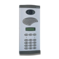
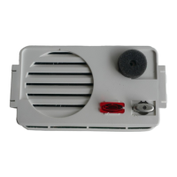
9670002 MAN - 050 Entrance panel with
mixed audio unit
4+N system
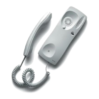
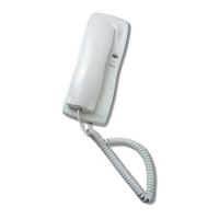
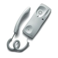
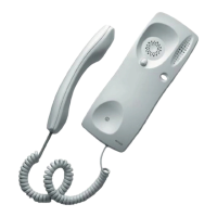
9600002 TUN - 001 Universal telephones
(electronic/buzzer)
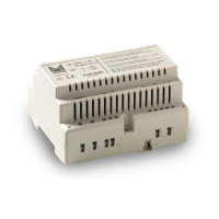
9620001 ALA - 040 Power supply
9730000 ABR - 001 Electric lock (other
models available)
CMO Flush-mounted box
coepending on
characteristics of
the installation)
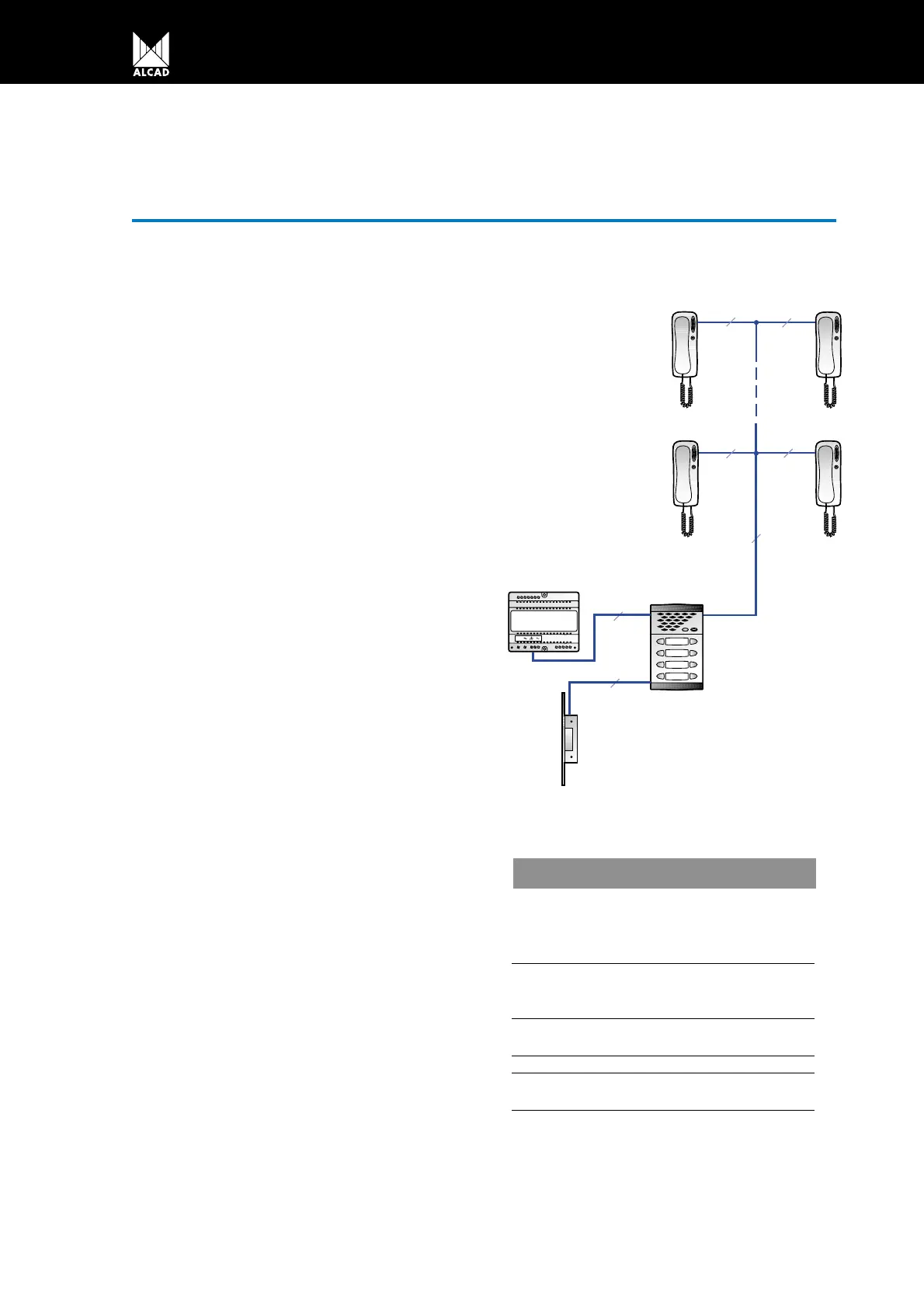
Basic circuit diagram of door entry system installa-
tion in buildings with a single entrance.
Operation
When one of the push buttons on the entrance
panel is pressed the call signal generated by the
audio unit (8) is sent via the call line to the corres-
ponding telephone (6) where it is heard. At the same
time the audio unit’s own loudspeaker generates a
sound to confirm to the visitor that the call has been
made.
When the handset is picked up the electronics
associated to the telephone’s audio lines (3 and 4) is
internally connected to the entrance panel. This co-
nnection sets up the communication between the tele-
phone and the entrance panel.
When the door lock release button on the telepho-
ne is pressed, the audio unit detects the closing of the
lock release circuit (1). The audio unit then sends an
a/c voltage (11 and 12) to the electric lock, thus allo-
wing the entrance door to be opened.
The common wire (2) of the telephone and entran-
ce panel provides the return path for all the telepho-
ne signals.
V230 V230 V
4+N
TUN-001
ALA-040
ABR-001
5
2
2
5
5
5
V
MAN-050
MPD-004
BASIC INSTALLATION WITH BUZZER CALL
4+N SYSTEM
 Loading...