54
Basic circuit diagram of a door entry system insta-
llation in a complex with several blocks.
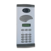
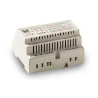
Alcad multiple entrance systems are based on the
use of microprocessor-controlled audio units (micro-
processor-based 4+N system). Rather than using
changeover switches to select one of the entrance
panels, the audio unit has been fitted with a micro-
processor that decides which entrance panel should
be activated, and deactivates the rest of the panels in
the system.
This system simplifies the cabling of the installation,
reduces the number of components and improves
system operation.
This type of installation can be treated as several ins-
tallations with two entrances each joined together. On
the main entrance to the complex or residential there
are as many entrance panels as buildings inside the
complex. Thus, each entrance panel at the main
entrance is associated dust with the entrance panel of
one of the buildings. Each pair of panels works in the
same way as a two-entrance installation.
Operation
Each entrance panel at the main entrance end is
selected as the main panel of the system. Just one
panel per installation can be defined as the main one.
To select it, remove jumper J1 from the buildings
entrance panels. The main panel is the one which is
connected by default to the system’s telephones. The
other panels are only activated when one of the call
buttons is pressed.
When a call button is pressed, the corresponding
panel is activated to allow communication with the
telephones. The system busy indicator light on the
associated panel will start to flash to indicate that it is
disabled. If the call is made from an entrance panel
from the main entrance to the residential, it´s possible
to disable not only the building associated to that
panel but also the rest of the panels of the main entran-
ce. To do so the various panels need to be interco-
nnected via terminal 16.
When one of the push buttons on one of the entran-
ce panels is pressed the electronic call signal genera-
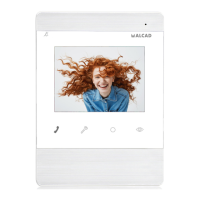
ted by the audio unit (7) is sent via the call line to the
corresponding telephone (5), where it is heard on the
loudspeaker of the handset. At the same time the
audio unit’s own loudspeaker generates a sound to
confirm to the visitor that the call has been made. The
audio unit also generates a control signal (17) that
deactivates the associated entrance panel. When the
visitor is calling from the main entrance, the audio unit
generates a control signal (16) which disables the rest
of the panels at the entrance.
The audio unit starts a 30 second timer while it waits
for the telephone handset to be picked up. If the hand-
set is not picked up during this time, the control signal
(17) and (16) (in the case of the main entrance) is
removed and the panels go into the standby state.
If the handset is picked up during this time, the elec-
tronics associated to the telephone’s audio lines (3
and 4) is internally connected to the entrance panel.
This connection sets up the communication between
the telephone and the entrance panel. The audio unit
starts a fresh 60 second period before removing the
control signals (17) and (16) (in the case of the main
entrance) and putting the panels into standby state.
When only 10 seconds are left a buzz will be heard.
It is possible to restart the timer from the dwelling end
by pressing and releasing the telephone handset’s
hook switch. After finishing the communication, when
the audio unit detects that the telephone handset has
been hung up, it removes the control signals (17) and
(16) (in the case of the main entrance) and the panels
go into the standby state.
When the door lock release button on the telepho-
ne is pressed, the active audio unit detects the closing
of the lock release circuit (1). The audio unit then
sends an a/c voltage (11 and 12) to the electric lock
connected to the active entrance panel, thus allowing
the entrance door to be opened.
The common wire (2) of the telephone and entran-
ce panel provides the return path for all the telephone
signals.
INSTALLATION WITH ELECTRONIC CALL IN A COMPLEX
WITH SEVERAL BLOCKS
MICROPROCESSOR-BASED 4+N SYSTEM

 Loading...