3-3
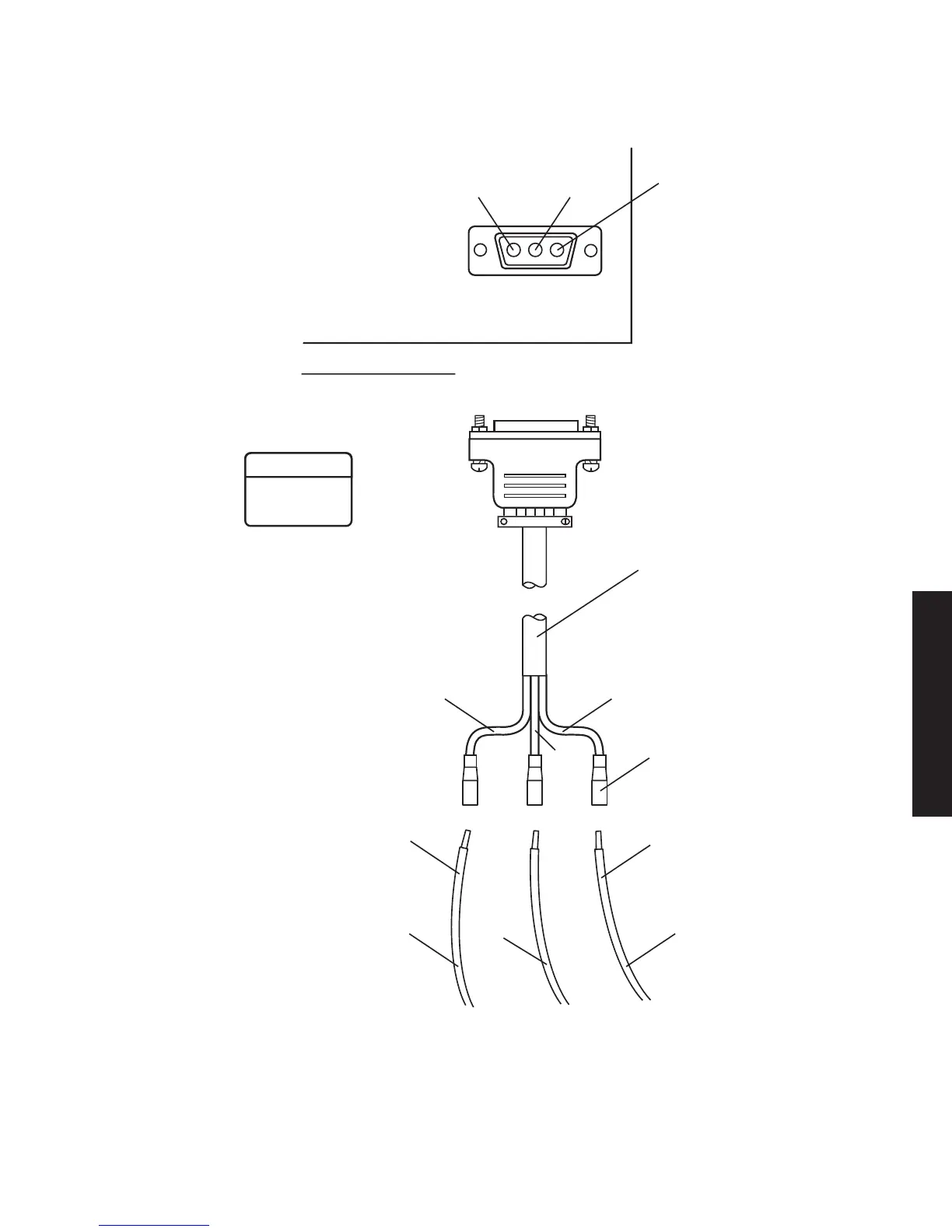
Figure 3 - 1 Power Cable Connection
PIN 1
POS
PIN 2
GND
J1
(J2 ON OPPOSITE
END OF SHELF)
PWR CABLE ASSEMBLY
PN 695-7845-005/009
SLIDE-ON
LUG
RED
12 AWG
LMW-3103F
11/20/06
CHASSIS
GND
– BATT
+ BATT
CONNECT + BATT WIRE
TO + RACK GND FOR
POS GND INSTALLATIONS
CONNECT – BATT WIRE
TO – RACK GND FOR NEG
GND INSTALLATIONS
PIN 3
NEG
ORN
12 AWG
ORN
BLK
RED
BLK
12 AWG
1. DETERMINE IF INSTALLATION
REQUIRES POS OR NEG GND.
2. INSTALL BATT, GND, AND JUMPER
WIRES ON PWR CABLE ASSEMBLY.
3. CONNECT PWR CABLE ASSEMBLY
TO J1 (AND J2 IF HOT-STBY).
4. CONNECT RACK GND AND
CHASSIS GND.
5. CONNECT BATT.
REAR VIEW OF SHELF
WARNING
Possibility of
Damage
To Equipment
To prevent connector damage and
improper wiring, ensure power cable
mating connector is properly oriented
and aligned with shelf connector
before attempting to seat connectors.