3-14
3.10 DS3 LBO WAYSIDE DS1 CONNECTIONS (J201 IN AND J202 OUT)
Wayside DS1 is an option in the MDR-8000 DS3 radios. This option provides 1 DS1 for
each equipped DS3. To activate the wayside channels requires a small circuit board, called
ELMC option key, that plugs onto the controller module. The protection of the wayside
channels follows the protection scheme of the radio configuration. In other words, if the
radio is hot-standby the wayside channels are hot-standby. The channels are point to point
just as is the payload traffic. They are independent of the traffic and reside in the overhead
channels. The advantage of the wayside DS1 is the ability to drop 1 to 3 DS1’s without hav
-
ing to add a 1:3 muldem to access the traffic. Refer to Table 3 - 6 for ELMC option key
requirements for remote monitoring/controlling wayside DS1s.
3.10.1 Wayside DS1 Terminal
Recommended connectorized cable assembly – PN 695-4125-041 (26 AWG 5 pair shielded,
jacketed cable with 9-pin D-type connector on one end. See
Figure 3 - 9 for shelf connector
location and pinout. Refer to Table 3 - 7 for mating cable wiring and color code.
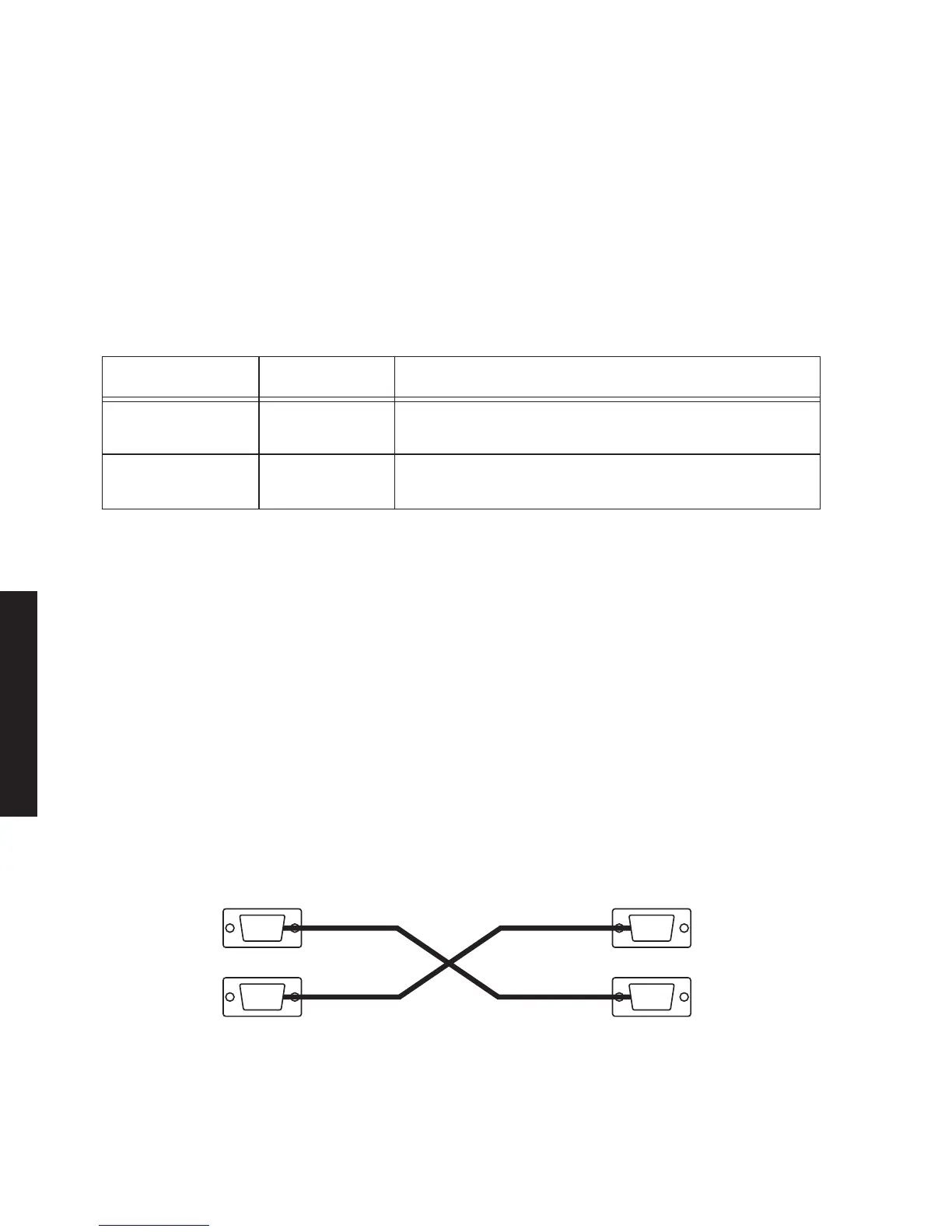
3.10.2 Wayside DS1 Repeater
Recommended connectorized cable assembly – PN 695-4125-051 (26 AWG 5 pair shielded,
jacketed cable with 9-pin D-type connector on each end). See
Figure 3 - 8 for Wayside DS1
repeater interconnect.
Figure 3 - 8 Wayside DS1 Repeater Interconnect
Table 3 - 6 Wayside DS1 Performance and Control
PART NO. FUNCTION
ELMC Option Key 695-5647-019 Required to enable WS DS1 lines for remote wayside
DS1status
ELMC Option Key 695-5647-020 Required to enable WS DS1 lines for remote wayside
DS1status + remote provisioning and downloading
SHELF 1
OUTPUT
INPUT
LMW-7071-sm
7/24/02
OUTPUT
INPUT
SHELF 2
J201
J202 J202
J201