EasyManuals Logo

Alcatel-Lucent OmniPCX Office Installation Manual

Alcatel-Lucent OmniPCX Office
230 pages
To Next Page IconTo Next Page
To Previous Page IconTo Previous Page
Page #127 background imageLoading...
Page #127 background image
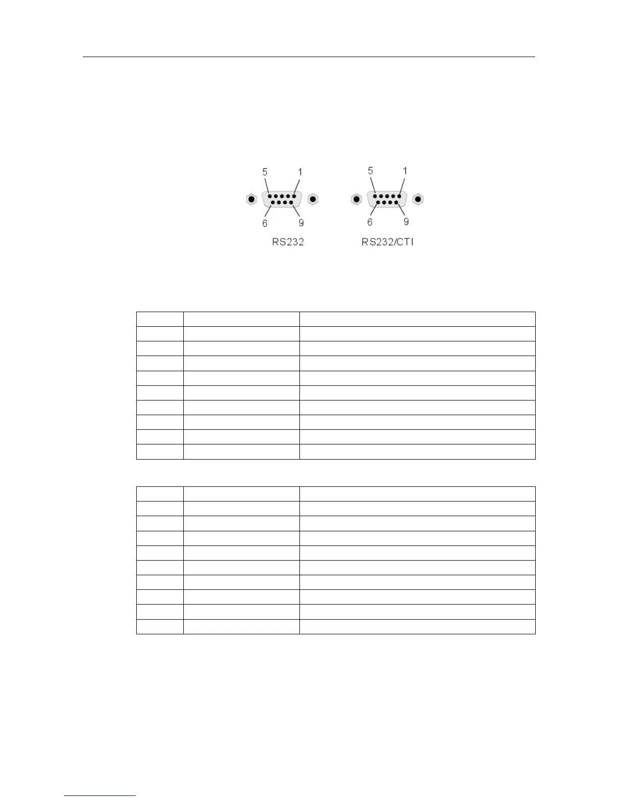
2. V24 SUBD9 connector
3. CTI SUBD9 connector
Figure 4.53: Connector Details
RS 232 port (V24):
Pin Signal Description
1 DCD Data Carrier Detect.
2 TX Transmit data.
3 RX Received data.
4 DTR Data Terminal Ready.
5 GND Protective ground.
6 DSR Data Set Ready.
7 RTS Request To Send.
8 CTS Clear To Send.
9 RI Ringing Indicator.
CTI port:
Pin Signal Description
1
2 TX Data transmission
3 RX Data reception
4
5 GND Protective ground
6
7 RTS Transmission request
8 CTS Ready for transmission
9
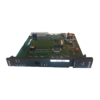
4.8 AP Interface Module
4.8.1 Hardware description
  ()
       
4-79

Table of Contents

Other manuals for Alcatel-Lucent OmniPCX Office

Questions and Answers:

Question and Answer IconNeed help?

Do you have a question about the Alcatel-Lucent OmniPCX Office and is the answer not in the manual?

Alcatel-Lucent OmniPCX Office Specifications

General IconGeneral
VoIP ProtocolsSIP, H.323
Power Supply100-240 VAC, 50/60 Hz
Humidity10% to 90% non-condensing
TypeIP PBX
Maximum TrunksUp to 60
Voice codecsG.711, G.729
Network Interfaces10/100 Ethernet
WeightVaries depending on the model/configuration

Related product manuals