OmniSwitch 6250 Series Hardware Users Guide September 2009 page 4-1
Preliminary
9/28/09
4 Booting 6250 Series
Switches
For information on booting stand-alone switches and switches in stacked configurations, refer to the
sections below.
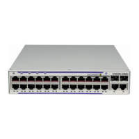
Booting an OmniSwitch 6250
The OmniSwitch 6250 Series switch does not use an on/off switch. The power cord is the switch’s only
connect/disconnect device. The power connector socket is located on the power supply rear panel. For
more information, refer to “OmniSwitch 6250 Series Chassis and Hardware Components” on page 2-1.
To boot the switch, plug the power cord into an easily-accessible power source, such as a grounded AC
outlet or an Uninterruptible Power Supply (UPS).
The switch immediately begins the boot process. Allow a few moments for the switch to boot completely,
then verify the status of all LEDs on the switch’s front panel. A successful boot displays the following
LED states:
If any of the LED state differs from the states shown in the table above, refer to page 2-7 for more infor-
mation. Contact Alcatel-Lucent Customer Support if the LED state persists.
For information on logging in and configuring your OmniSwitch 6250 Series switch, refer to the
OmniSwitch 6250 Series Getting Started Guide.
LED States for a Stand-Alone Switch
OK Solid green
PRI Solid green
STK Amber
PWR Solid Green
BPS Solid green or OFF if no backup power supply is connected.
LED States for a Stacked Switch
OK Solid green
PRI Solid green (primary); Amber (Secondary); Off (Idle)
STK Green
PWR Solid Green
BPS Solid green or OFF if no backup power supply is connected.
 Loading...


